Catalyst QoS: The 3550 Explained
QoS features available on Catalyst switch platforms have specific limitations, dictated by the hardware design of modern L3 switches, which is heavily optimized to handle packets at very high rates. Catalyst switch QoS is implemented using TCAM (Ternary Content Addressable Tables) - fast hardware lookup tables - to store all QoS configurations and settings. We start out Catalyst QoS overview with the old, long time available in the CCIE lab, the Catalyst 3550 model.
To begin with, the Catalyst 3550 sees the world as consisting of IP and non-IP (e.g. ARP, IPv6, IPX) packets – the distinction being made based on the Ethertype value in incoming Ethernet frame. This peculiarity is due to the fact that 3550 is a Layer 3 switch, designed to route IP packets in addition to the regular L2 switching. The feature has some impact on QoS classification options of 3550 as we shall see later.
The Catalyst 3550 QoS model is based on Diff-Serv architecture, where each packet is classified and marked, to encode the class value. Packets are given a per-hop treatment at every network node, based on their class (marking). With Diff-Serv architecture, classification and admission control are performed at network (Diff-Serv domain) edges, while network core is used to implement the QoS procedures based on packet classes.
The Catalyst 3550 is capable of performing either Diff-Serv boundary device functions (classification, marking & admission control) or Diff-Serv interior device functions (e.g. queueing & scheduling). Catalyst 3550 understands the following types of marking: 802.1p priority bits (available on trunk ports only) and IP ToS byte (IP packets only) – the latter could be interpreted as either DSCP (64 values) or IP Precedence (8 values). While IP Precedence and DSCP values are naturally applicable to IP packets, CoS is the only possible “transit” (inter-switch) marking available to non-IP packets (in the sense 3550 interprets them).
One may ask, why is the difference between IP Precedence and DSCP when the former seems to be a subset of DSCP classes space? Actually it is true – IP Precedence value x numerically maps directly to CSx under DSCP nomenclature. However, the semantics of IPP and DSCP are different. If we interpret packets under the “Precedence” model (which is old, military based QoS model – Internet begun as a military project, remember?) we should treat it differently then if we were interpreting it under the CSx class of Diff-Serv model. This is why IP Precedence and DSCP marking are usually considered separately.
To finish with marking, keep in mind, that IP packet may come in with both CoS (taken from dot1q/ISL header) and DSCP/IP Precedence values set. Therefore, a Catalyst switch needs a way to handle both markings at the same time. (We’ll discuss this feature in more details later). (Side-note: QoS features on 3550 switch are enabled with the global mls qos command. As soon as you entered this command, all classification settings are set to their default values, and in effect all packets traversing the switch will have their CoS and DSCP values set to zero)
Now, the QoS flowchart for the 3550 Catalyst switch looks as follows:
Stage 1 (Ingress): Classify, Police & Mark.
The goal of this stage is to mark a packet - deduce an internal DSCP value for whatever type of packet (IP or non-IP) has arrived. (Note that we may consider “drop action” as a special kind of “marking” too). Internal DSCP is “unified” marking scheme used inside the switch to perform any QoS-related processing. To deduce the internal DSCP value for non-IP packets (e.g. IPv6), which could only be marked using the CoS field, a special configurable (switch-global) CoS to DSCP translation table is used. This table is applied whether we use CoS to classify an incoming packet, be it IP or non-IP - more on that later.
For IP packets, the new internal DSCP value replaces the original DSCP field in a packet. For non-IP packets, new CoS value is calculated for packets from the internal DSCP using a configurable DSCP to CoS table (which is global to a switch). The latter table is also used on the scheduling stage, to determine egress Queue-ID.
Specifically, to classify non-IP packets a Catalyst switch may either:
a) Trust the CoS value from incoming frame on a trunk link (keep the CoS value encoded in a frame). This option is only applicable to trunk links. (You may consider voice VLAN dot1p option as a rudimentary trunk also).
b) Use the default CoS value assigned to a port. This action is used when no CoS value is present in incoming packet and you configure to trust CoS .You may use this option on either access or trunk links (e.g. 802.1q native VLAN). The default “CoS default” value is zero. You may set it with mls qos cos interface-level command.
A few words on “CoS override mode”. When you configure mls qos cos X override under interface, all packets entering the interfaces are assigned this CoS value, irrespective of any other QoS settings (e.g. trust states). Use this command to quickly assign a “precedence” level to all packets entering an interfaces.
c) Classify and assign CoS value based on QoS ACLs. You may configure and apply QoS ACL (actually, it’s just a regular ACL) using an ingress policy-map on 3550 switch. Packets matching the ACL are then either trusted, assigned CoS value manually, and/or policed. For non-IP packets you may only use MAC extended access-lists for classification. Note that due to 3550 “blindness” you may only use MAC ACLs to classify only the non-IP packets – MAC ACLs won’t work with the IP packets!
After the CoS value has been deduced for non-IP packet, it is then translated into internal DSCP value by using the configurable CoS to DSCP table. Here is an example:
!
! CoS -> DSCP mapping table, define 8 DSCP values here (CoS 0..7)
!
mls qos map cos-dscp 16 8 16 24 32 46 48 56!
! MAC access-list to match ARP (non IP) packets
!
mac access-list extended ARP
permit any any 0x806 0x0
!
class-map ARP
match access-group name ARP!
! Assign CoS 3 to ARP packets and police
!
policy-map CLASSIFY
class ARP
set cos 3!
! Attach service-policy ingress
!
interface FastEthernet 0/4
mls qos trust cos
service-policy input CLASSIFY
mls qos cos 1
More classification options are available for IP packets. First, as mentioned above, an IP packet may arrive encapsulated in Ethernet frame with dot1q or ISL header. That means we may obtain the current marking either from CoS or IP Precedence/DSCP bits. Here is a full list:
a) Trust CoS value for an incoming packet. The CoS to DSCP translation table is then used to deduce the internal DSCP value. You may optionally configure special DSCP pass-through mode with the mls qos trust cos pass-through dscp command. When this mode is active, internal DSCP value is deduced from the CoS field, and all QoS operations are based on it. However, the original DSCP value in packet is not getting overwritten with the new DSCP deduced from CoS field. This feature also works backwards: you may trust DSCP value for an IP packet (discussed later) and leave CoS value untouched, passing it transparently.
b) Use the default CoS value assigned to a port. This option only works if you configure to trust CoS and CoS value is not present in the incoming packet.
c) Trust IP Precedence. Takes the IP Precedence field from the IP packet header, and convert it to internal DSCP value using the configurable IP Precedence to DSCP mapping table. This is pretty straightforward.
d) Trust DSCP value. The DSCP value from an IP packet header is retained and used as internal DSCP. As mentioned above, you may disable CoS rewrite according to DSCP to CoS tables by issuing global-mode command mls qos trust dscp pass-through cos.
d) Use QoS ACLs for classification. You may use standard or extended IP access-list to match incoming packets by applying them with MQC class-maps and policy-maps. Matched packets could be trusted, marked and/or policed. Note that due to TCAM capacity limits you may not be able to fit arbitrary large QoS ACL into hardware.
e) IP packets that did not fall under any of the previous classification options are assigned the DSCP value of zero (best-effort traffic).
!
! IP extended ACL to match ICMP traffic
!
ip access-list extended ICMP
permit icmp any any
!
class-map ICMP
match access-group ICMP!
! TCP traffic
!
ip access-list extended TCP
permit tcp any any
!
class-map TCP
match access-group TCPpolicy-map CLASSIFY
!
! Classification combined with policing
!
class ICMP
set ip dscp 26
police 64000 8000
class TCP
trust ip-precedence!
! Attach service-policy ingress
!
interface FastEthernet 0/4
mls qos trust dscp
service-policy input CLASSIFY
mls qos cos 1
Ingress Policing
Catalyst 3550 switches allow to apply ingress policing to various traffic classes, using DSCP values or IP/MAC ACLs to classify traffic (the latter option is the only one available to non-IP packets). Policing could be combined with marking, by using the MQC policy-maps syntax (set command). You may apply up to 8 ingress policers on any port and up to 8 egress policers. Note, that egress policers support only DSCP-based classification. On GigabitEtherner interfaces number of ingress policers is bigger, but still limited to 128.
A policer in Catalyst 3550 is defined by its average rate, burst size and exceed action. The larger is the burst size, the more tolerable is policer to accident traffic rate “spikes”. No formula exists for optimal burst size - it’s usually calculated basic on empirical results. However, a common recommendation is to configure the burst size to no less than AverageRate*1,5s bytes, since this parameter is suitable for heavy TCP traffic flows (avoids excessive drops and TCP slow-start behavior). Due to the fact that policers are implemented in hardware, you may find that IOS rounds up your burst size to a value more suited for ASIC based implementation.
Exceed actions include drop and markdown (policed DSCP transmit). When you apply a markdown action under a policer, a special global configurable table is used to map an internal DSCP to it’s policed equivalent. E.g. you may want to police down exceeding user traffic from CS0 (e.g. best-effort) to CS1 (e.g. Scavenger). Default markdown settings are to keep DSCP values the same.
Policer could be of two types – individual or aggregate. Individual policer is configured under a class-map assigned under a policy map, and applies only to a single traffic class. Aggregate policers are defined globally, using special command syntax, and shared among multiple classes, configured under a policy map attached to an interface. That is, traffic under all classes configured to share an aggregate policer is policed under the same policer settings. Note that you can’t share an aggregate policer among different ports.
!
! Global markdown configuration
!
mls qos map policed-dscp 0 46 to 1
!
ip access-list extended ICMP_4
permit icmp any host 150.15.4.4
!
ip access-list extended ICMP_44
permit icmp any host 150.15.44.44
!
class-map ICMP_4
match access-group name ICMP_4
!
class-map ICMP_44
match access-group name ICMP_44
!
!
!
mls qos aggregate-policer AGG1 16000 8000 exceed-action policed-dscp!
! Set the default DSCP to 0, remark to CS1 on exceed
!
policy-map INGRESS_R3
class ICMP_4
set ip dscp 0
police aggregate AGG1
class ICMP_44
set ip dscp 0
police aggregate AGG1
Per-Port Per-VLAN (PPPV) classification
The classification options we considered so far are “port-wise” - i.e. they apply to all traffic arriving on a port, whether it is trunk or access link. However, 3550 switches have special feature called per-por per-VLAN classification, which allows applying a QoS ACL classification method on a per-VLAN basic to a specific port.
PPPV requires a very strict syntax for its configuration. Failing to obey the order of operations will result in non-working and rejected configuration. First, you need to define a class-map to match traffic “inside” a VLAN. This class-map could be based on an IP/MAC ACL or simply match a range of DSCP values. For example:
class-map VOICE_BEARER

 match ip dscp ef
Next you create a second, “parent” class-map, that matches a specific VLAN or VLAN range. The first entry under this class-map must be a match vlan statement. The second (and the last entry) should be match class-map entry, that matches traffic “inside” a VLAN or VLAN range:
class-map match-all VLAN_34_VOICE

 match vlan 34

 match class-map VOICE_BEARER
You then assign the “parent” classes to a policy-map. Note that all classes under this policy-map must contain match vlan as their first entry, and match class-map as their second entry.
class-map SCAVENGER
match ip dscp 1
!
class-map VLAN_43_SCAVENGER
match vlan 43
match class-map SCAVENGER!
! Per VLAN policy-map
!
policy-map PER_VLAN_POLICY
class VLAN_34_VOICE
police 128000 32000 exceed policed-dscp
class VLAN_43_SCAVENGER
police 64000 16000 exceed dropinterface FastEthernet 0/3
service-policy input PER_VLAN_POLICY
Stage 2 (Egress): Police, Queue & Schedule
Packets arrive on egress with internal DSCP value assigned. Note that security ACL are matched against the original DSCP value, not the one imposed by classification process – this is due to the fact that QoS and Security ACLS are looked up through TCAM in parallel. Therefore VLAN access-map may block your packet based on it’s DSCP original value, no the one assigned by QoS ACLs. So now that packet has arrived to output port, 3550 performs the following:
a) Police traffic stream, based on DSCP value solely. No other classification option exists for egress policers. Note that you are allowed to mix ingress and egress policers on the same interface.
class-map SCAVENGER

 match ip dscp 1

!

policy-map POLICE_SCAVENGER

 class SCAVENGER

  police 64000 8000

!

interface FastEthernet 0/3

 service-policy output POLICE_SCAVENGER
b) Assign a packet to an output queue. 3550 defines 4 output queues (IDs from 1 to 4) for each interface, and packets are assigned to a queue using CoS to Queue-ID interface-level mapping table. Since packet handling is based on internal DSCP value, this value should be mapped to a CoS value, using yet another mapping table (this time global), called DSCP to CoS mapping table (there exists a default mapping, of course). Therefore, to assign a packet to an output queue, two lookups are made: DSCP->CoS & CoS->Queue-ID.
!

! DSCP->CoS global mapping table

!

mls qos map dscp-cos 56 4

!

interface FastEthernet 0/3

!

! CoS to Queue-ID mappings

!

 wrr-queue cos-map 1 0 1

 wrr-queue cos-map 2 2

 wrr-queue cos-map 3 3 6 7

 wrr-queue cos-map 4 5
Next, a check is performed to see if a selected queue has enough buffer space to accommodate another packet. If no space is available, packet is dropped. Buffer space is allocated to queues in the following manner:
For FastEthernet ports, you may configure up to 8 global levels - each level has a numeric value assigned, representing the number of packets allowed on a queue. You may then assign a level to a queue-id on per-interface basis. This limits the per-port flexibility, but is more optimized for hardware handling. The default assignment of levels to queue-ids is 1-4 to 1-4.
mls qos min-reserve 1 170

!

interface FastEthernet 0/3

 wrr-queue min-reserve 1 4

 wrr-queue min-reserve 2 3

 wrr-queue min-reserve 3 2

 wrr-queue min-reserve 4 1
For GigabitEthernet interface, you may configure the queue sizes directly under the interface configuration mode - no global levels need to be referenced. Simply specify how you want to divide the buffer pool of the gigabit port among the queues, by assigning each queue a relative weight value (not an absolute count of packets in queue!).
interface GigabitEthernet 0/1

  wrr-queue queue-limit 20 20 20 40
Packet drop procedure is not as simple as it may seems like. First, for FastEthernet interfaces you are only limited to a simple tail-drop, where the last packet not fitting in a queue is dropped. However, 3550 makes this simple algorithm more flexible – you are allowed to configure to start dropping packets before the queue is actually full. For every queue, it is possible to assign two thresholds – in percents of queue size. If the current queue size exceeds the threshold, new packets are dropped. Why two thresholds? To introduce yet another mapping table! Yes, you can map internal DSCP values to queue-size thresholds – within the interfaces scope - for all queue-ids simultaneously.
This way, you may configure to start dropping “unimportant” packets sooner, say when queue is 80% full, and drop important packets only when the queue is absolutely 100% full (remember you have 64 DSCP classes and just 4 queues - you cant guarantee a queue to every class!). This differentiated drop behavior is actually required per the Diff-Serv model, allowing implementing of different drop precedence for different classes.
interface FastEthernet 0/3

 !

 ! wrr-queue threshold queue-id thresh1% thresh2%

 !

 wrr-queue threshold 1 80 100

 wrr-queue threshold 2 80 100

 wrr-queue threshold 3 50 100

 !

 ! wrr-queue dscp-map threshold-id dscp1, … , dscp8

 !

 wrr-queue dscp-map 2 46 56 48

 wrr-queue dscp-map 1 0 8 16 24 34
By default, all DSCP values are mapped to threshold 1 and the threshold value is set to 100% of queue size.
For GigabitEthernet intrefaces (uplinks), you may use the same tail-drop procedure, or configure more advanced WRED (Weighted Random Early Detection) as drop policy. Describing WRED in details is beyond the scope of this document, but in short, it allows starting packet drops randomly, before the queue size reaches the configured threshold. This random behavior is specifically designed to overcome TCP over congestion and synchronization problems on loaded links. As with the tail-drop behavior, you may configure two WRED thresholds for each queue, and then map DSCP values to each threshold on per-interface basis. Packet drop probability increases as the queue size reaches the configured threshold.
interface GigabitEthernet 0/1

!

! wrr-queue random max-thresh queue-id thresh1% thresh2%

!

 wrr-queue random-detect max-threshold 1 80 100

 wrr-queue random-detect max-threshold 2 70 100

 wrr-queue random-detect max-threshold 3 70 100

 wrr-queue dscp-map 2 46 56 48

 wrr-queue dscp-map 1 0 8 16 24 34
c) Schedule/services packets on queue. Now that the packet has been queued, all the interfaces queues are serviced in a round-robin fashion, which is the simplest approximation to the “ideal” GPS (Generalized Processor Sharing) algorithm. The reason to choose such simple scheduler is the need for wire-speed latency of hardware packet switching. You just can’t implement WFQ or CBWFQ effectively for high-density port devices like a L3 switches due to the algorithms higher complexity. However, the scheduler used is not that primitive. Rather, it uses weighted round robin (WRR) to service interface queues. That means, you can assign up to four weights, one to each of the queues, and the scheduler will then service the queues in accordance to their weights.
Say if you assigned weigh values “10 20 30 40” to queues 1, 2, 3 and 4 then every round scheduler will take up to 10 packets from queue 1, no more than 20 packets from queue 2 etc. This way, all queues are services in a very effective manner, which still allows implementing Assured Forwarding behavior per the Diff-Serv model requirements. Note, that WRR does not limit the upper bound of packet rates – it only ensures it queue is services proportional to it’s weight, when interface is heavily congested. Under normal conditions, a queue could claim more bandwidth, than it’s configured by the use of it’s weight. The default weight values are 25 25 25 25. Side Note: The WRR description given here is not the classic WRR algorithm; the latter requires the average packet size for each queue to be known in ahead, in order to adjust weights and provide fairness. Therefore, per the DocCD description, we may assume that scheduling implemented is not the classic WRR, but rather a simplified form of it.
interface FastEthernet 0/3

 wrr-queue bandwdith 10 20 30 40
The last component to interface queue scheduler is priority queue. With each interface, you may configure queue-id 4 to be treated as priority. This means, whether you have any packets on queue-id 4, this queue is always empties first, no matter how many packets are there. Only then the regular WRR queues gets services. Expedite (priority) queue is enabled with priority-queue out command at inerface level:
interface FastEthernet 0/3

!

!  With PQ enabled, you may assign any weight to queue-id 4

!

 wrr-queue bandwdith 10 20 30 1

 priority-queue out
Note that when you have priority-queue enabled, you may configure any WRR weigth for this queue-id (4) – it is not taken in account when servicing WRR queues.
Basically, these are all the important details about 3550 QoS. We did not mention things like DSCP mutations maps, and some other minor features. However, the entire core QoS processing has been described and, hopefully, been made clear to a reader.
Further Reading
Understanding QoS Policing and Marking on the Catalyst 3350
Illustration
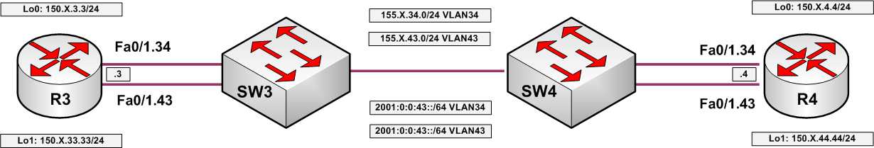
Consider the following test topology:

With the next example we will classify three traffic types on a single port: RIP updates, ICMP packets and IPv6 traffic. We will use policy-map to assign the IP precedence and CoS values to the packets accordingly.
SW3:
ip access-list extended RIP
permit udp any any eq 520
!
ip access-list extended ICMP
permit icmp any any!
! IPv6 Ethertype is 0x86DD
!
mac access-list extended IPV6
permit any any 0x86DD 0x0class-map RIP
match access-group name RIP
!
class-map ICMP
match access-group name ICMP
!
class-map VOICE
match ip dscp ef
!
class-map IPV6
match access-group name IPV6!
! Classify and police ingress traffic on the link to R3
!
policy-map CLASSIFY
class RIP
set ip precedence 3
class ICMP
set ip precedence 4
police 32000 8000 exceed drop
class IPV6
set cos 5
police 32000 8000 exceed drop
!
mls qos map cos-dscp 0 8 16 24 32 46 48 56
!
!
interface FastEthernet 0/3
service-policy input CLASSIFY
Verification: Create an access-list on R4 to match the IP packets
R4:

no ip access-list extended MONITOR_34

ip access-list extended MONITOR_34

 permit udp any any eq 520 precedence 3

 permit icmp any any precedence 4

 permit ip any any

!

interface FastEthernet 0/1.34

 ip access-group MONITOR_34 in
Send ICMP packet at a rate enough to kick in the policer exceed action:
Rack15R3#ping 155.15.34.4 repeat 50 size 1000

Type escape sequence to abort.

Sending 50, 1000-byte ICMP Echos to 155.15.34.4, timeout is 2 seconds:

!!!!!!!!!.!!!!!!!!.!!!!!!!!.!!!!!!!!.!!!!!!!!.!!!!

Success rate is 90 percent (45/50), round-trip min/avg/max = 4/4/9 ms
And verify the access-list at R4:
Rack15R4#show ip access-lists MONITOR_34

Extended IP access list MONITOR_34

    10 permit udp any any eq rip precedence flash (18 matches)

    20 permit icmp any any precedence flash-override (135 matches)

    30 permit ip any any (9 matches)
To check if IPv6 packets are matched by MAC access-list, send highly saturated stream of ICMPv6 echo packets to R4:
Rack15R3#ping 2001:0:0:34::4 repeat 50 size 1000 timeout 1

Type escape sequence to abort.

Sending 50, 1000-byte ICMP Echos to 2001:0:0:34::4, timeout is 1 seconds:

!!!!!!!!!.!!!!.!!!!.!!!!.!!!!.!!!!.!!!!.!!!!.!!!!.

Success rate is 82 percent (41/50), round-trip min/avg/max = 4/7/8 ms
