Quick Notes on the 3560 Egress Queuing
The goal of this article is to discuss how would the following configuration work in the 3560 series switches:
interface FastEthernet0/13

 switchport mode access

 load-interval 30

 speed 10

 srr-queue bandwidth shape 50 0 0 0

 srr-queue bandwidth share 33 33 33 1

 srr-queue bandwidth limit 20
Before we begin, let’s recap what we know so far about the 3560 egress queuing:
1) When SRR scheduler is configured in shared mode, bandwidth allocated to each queue is based on relative weight. E.g. when configuring "srr-queue bandwidth share 30 20 25 25" we obtain the weight sum as 30+20+25+25 = 100 (could be different, but it’s nice to reference to “100”, as a representation of 100%). Relative weights are therefore “30/100”, “20/100”, “25/100”, “25/100” and you can calculate the effective bandwidth *guaranteed* to a queue multiplying this weight by the interface bandwidth: e.g. 30/100*100Mbps = 30Mbps for the 100Mbps interface and 30/100*10Mbps=3Mbps for 10Mbps interface. Of course, the weights are only taken in consideration when interface is oversubscribed, i.e. experiences a congestion.
2) When configured in shaped mode, bandwidth restriction (policing) for each queue is based on inverse absolute weight. E.g. for “srr-queue bandwidth shape 30 0 0 0” we effectively restrict the first queue to “1/30” of the interface bandwidth (which is approximately 3,3Mbps for 100Mbps interface and approximately 330Kbps for a 10Mbps interface). Setting SRR shape weight to zero effectively means no shaping is applied. When shaping is enabled for a queue, SRR scheduler does not use shared weight corresponding to this queue when calculating relative bandwidth for shared queues.
3) You can mix shaped and shared settings on the same interface. For example two queues may be configured for shaping and others for sharing:
interface FastEthernet0/13

 srr-queue bandwidth share 100 100 40 20

 srr-queue bandwidth shape  50  50  0  0
Suppose the interface rate is 100Mpbs; then queues 1 and 2 will get 2 Mbps, and queues 3 and 4 will share the remaining bandwidth (100-2-2=96Mbps) in proportion “2:1”. Note that queues 1 and 2 will be guaranteed and limited to 2Mbps at the same time.
4) The default “shape” and “share” weight settings are as follows: “25 0 0 0” and “25 25 25 25”. This means queue 1 is policed down to 4Mbps on 100Mpbs interfaces by default (400Kbps on 10Mbps interface) and the remaining bandwidth is equally shared among the other queues (2-4). So take care when you enable “mls qos” in a switch.
5) When you enable “priority-queue out” on an interface, it turns queue 1 into priority queue, and scheduler effectively does not account for the queue’s weight in calculations. Note that PQ will also ignore shaped mode settings as well, and this may make other queues starve.
6) You can apply “aggregate” egress rate-limitng to a port by using command “srr-queue bandwidth limit xx” at interface level. Effectively, this command limits interface sending rate down to xx% of interface capacity. Note that range starts from 10%, so if you need speeds lower than 10Mbps, consider changing port speed down o 10Mbps.
How will this setting affect SRR scheduling? Remember, that SRR shared weights are relative, and therefore they will share the new bandwidth among the respective queues. However, shaped queue rates are based on absolute weights calculated off interface bandwidth (e.g. 10Mbps or 100Mbps) and are subtracted from interface “available” bandwidth. Consider the example below:
interface FastEthernet0/13

 switchport mode access

 speed 10

 srr-queue bandwidth shape 50 0 0 0

 srr-queue bandwidth share 20 20 20 20

 srr-queue bandwidth limit 20
Interface sending rate is limited to 2Mbps. Queue 1 is shaped to 1/50 of 10Mps, which is 200Kbps of bandwidth. The remaining bandwidth 2000-200=1800Kbps is divided equally among other queues in proportion 20:20:20=1:1:1. That is, in case on congestion and all queues filled up, queue 1 will get 200Kbps, and queues 2-4 will get 600Kbps each.
Quick Questions and Answers
Q: How would I determine which queue will the packet go to? What if my packet has a CoS and DSCP value set at the same time?
A: That depends on what you are trusting at classification stage. If you trust CoS value, then QoS to Output Queue map will be used. Likewise, if you trust DSCP value, then DSCP to Output Queue map will determine the outgoing queue. Use “show mls qos map” commands to find out the current mappings.
Q: What if I’ve configured “shared” and “shaped” srr-queue settings for the same queue?
A: The shaped queue settings will override shared weight. Effectively, shared weight will also be exempted from SRR calculations. Note that in shaped mode queue is still guaranteed it’s bandwidth, but at the same time is not allowed to send above the limit.
Q: What if priority-queue is enabled on the interface? Can I restrict the PQ sending rate using “shaped” weight?
A: No you can’t. Priority-queue will take all the bandwidth if needed, so take care with traffic admission.
Q: How will a shaped queue compete with shared queues on the same interface?
A: Shared queues share the bandwidth remaining from the shaped queues. At the same time, shaped queues are guaranteed the amount of bandwidth allowed by their absolute weight.
Q: How is SRR shared mode different from WRR found in the Catalyst 3550?
A: SRR in shared mode essentially behaves similar to WRR, but is designed to be more efficient. Where WRR would empty the queue up to it’s credit in single run, SRR will take series of quick runs among all the queues, providing more “fair” share and smoother traffic behavior.
Verification scenario diagram and configs

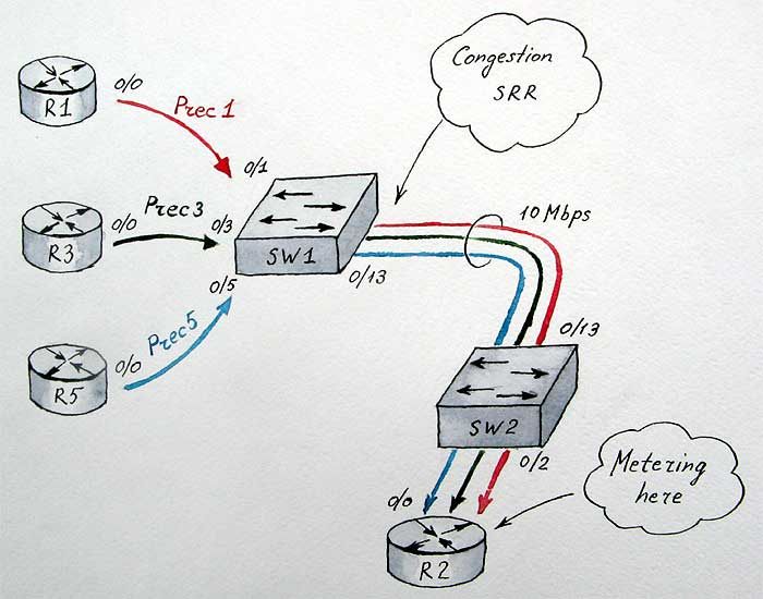
For the lab scenario, we configure R1, R3 and R5 to send traffic down to R2 across two 3560 switches saturating the link between them. All routers share one subnet 172.16.0.X/24 where X is the router number. SW1 will assign CoS/IP Precedence values of 1, 3 and 5 respectively to traffic originated by R1, R3 and R5. At the same time, SW1 will apply egress scheduling on it’s connection to SW2. R2’s function is to meter the incoming traffic, by matching the IP precedence values in packets. Note that SW2 has mls qos disabled by default.
We will use the default CoS to Output Queue mappings with CoS 1 mapped to Queue 2, CoS 3 mapped to Queue 3 and CoS 5 mapped to Queue 1. Note that by the virtue of the default mapping tables, CoS 0-7 map to IP Precedence 0-7 (which become overwritten), so we can match IP precedence’s on R2.
SW1#show mls qos maps cos-output-q

   Cos-outputq-threshold map:

              cos:  0   1   2   3   4   5   6   7

              ------------------------------------

  queue-threshold: 2-1 2-1 3-1 3-1 4-1 1-1 4-1 4-1
SW1’s connection to SW2 is set to 10Mbps port rate, and further limited down to 2Mps by the use of “srr bandwidth limit” command. We will apply different scenarios and see how SRR behaves. Here comes the configurations for SW1 and R2:
SW1:
interface FastEthernet0/1
switchport mode access
load-interval 30
mls qos cos 1
mls qos trust cos
spanning-tree portfast
!
interface FastEthernet0/3
switchport mode access
load-interval 30
mls qos cos 3
mls qos trust cos
spanning-tree portfast
!
interface FastEthernet0/5
load-interval 30
mls qos cos 5
mls qos trust cos
spanning-tree portfastR2:
class-map match-all PREC5
match ip precedence 5
class-map match-all PREC1
match ip precedence 1
class-map match-all PREC3
match ip precedence 3
!
!
policy-map TEST
class PREC5
class PREC3
class PREC1
!
access-list 100 deny icmp any any
access-list 100 permit ip any any
!
interface FastEthernet0/0
ip address 172.16.0.2 255.255.255.0
ip access-group 100 in
load-interval 30
duplex auto
speed auto
service-policy input TEST
To simulate traffic flow we execute the following command on R1, R3 and R5:
R1#ping 172.16.0.2 repeat 100000000 size 1500 timeout 0
In the following scenarios port speed is locked to 10Mbps and additionally port is limited to 20% of the bandwidth, with the effective sending rate of 2Mbps.
First scenario: Queue 1 (prec 5) is limited to 200Kbps while Queue 2 (prec 1) and Queue 3 (prec 3) share the remaining bandwidth in equal proportions:
SW1:
interface FastEthernet0/13
switchport mode access
load-interval 30
speed 10
srr-queue bandwidth share 33 33 33 1
srr-queue bandwidth shape 50 0 0 0
srr-queue bandwidth limit 20R2#sh policy-map interface fastEthernet 0/0 | inc bps|Class
Class-map: PREC5 (match-all)
30 second offered rate 199000 bps
Class-map: PREC3 (match-all)
30 second offered rate 886000 bps
Class-map: PREC1 (match-all)
30 second offered rate 887000 bps
Class-map: class-default (match-any)
30 second offered rate 0 bps, drop rate 0 bps
Second Scenario: Queue 1 (prec 5) is configured as priority and we see it leaves other queues starving for bandwidth:
SW1:
interface FastEthernet0/13
switchport mode access
load-interval 30
speed 10
srr-queue bandwidth share 33 33 33 1
srr-queue bandwidth shape 50 0 0 0
srr-queue bandwidth limit 20
priority-queue outR2#sh policy-map interface fastEthernet 0/0 | inc bps|Class
Class-map: PREC5 (match-all)
30 second offered rate 1943000 bps
Class-map: PREC3 (match-all)
30 second offered rate 11000 bps
Class-map: PREC1 (match-all)
30 second offered rate 15000 bps
Class-map: class-default (match-any)
30 second offered rate 0 bps, drop rate 0 bps
Third Scenario: Queues 1 (prec 5) and 2 (prec 1) are shaped to 200Kbps, while Queue 3 (prec 3) takes all the remaining bandwidth:
SW1:
interface FastEthernet0/13
switchport mode access
load-interval 30
speed 10
srr-queue bandwidth share 33 33 33 1
srr-queue bandwidth shape 50 50 0 0
srr-queue bandwidth limit 20R2#sh policy-map interface fastEthernet 0/0 | inc bps|Class
Class-map: PREC5 (match-all)
30 second offered rate 203000 bps
Class-map: PREC3 (match-all)
30 second offered rate 1569000 bps
Class-map: PREC1 (match-all)
30 second offered rate 199000 bps
Class-map: class-default (match-any)
30 second offered rate 0 bps, drop rate 0 bps
