PVST+ Explained
Cisco switches run different types of STP protocol, depending on whether the connected port is access, ISL trunk or 802.1q trunk. Natively, Cisco switch runs a separate STP instance for each configured and active VLAN (this is called Per-VLAN Spanning Tree or PVST) and standard IEEE compliant switches run just one instance of STP shared by all VLANs. Due to that reason, a group of switches running IEEE compatible STP protocol is called MST (Mono Spanning Tree) region, not to be confused with MSTP (multiple spanning tree).
Access Ports. Cisco switches run the IEEE version of STP protocol on the access ports. The IEEE STP BPDUs are sent to IEEE reserved multicast MAC address “0180.C200.0000” using IEEE 802.2 LLC SAP encapsulation with both SSAP and DSAP fields equal to “0x42”. (By the way, for the purpose of Layer2 filtering, IEEE BPDUs could be matched using a MAC ACL with LSAP value of ”0x4242”). Note that you can plug any standard IEEE compliant switch into a Cisco switch access port and they will inter-operate perfectly, joining the respective access VLAN's STP instance with the IEEE STP instance (MST).
ISL Trunks. Cisco switches run PVST (Per-VLAN Spanning Tree) on ISL trunk links. The same IEEE STP BPDUs are sent for each VLAN, encapsulated with additional ISL header, which also carries the VLAN number. The magic part is that ISL header has special flag to distinguish frames carrying STP BPDUs and this is how PVST can re-use the regular IEEE BPDUs to simulate multiple spanning trees. Since PVST BPDUs have the same format as IEEE BPDUs (that is IEEE 802.2 LLC SAP) they can be matched using the same SSAP/DSAP values of “0x42” for the purpose of Layer 2 filtering.The group of Cisco switches connected using ISL trunks only is called PVST region.
802.1q Trunks. Cisco switches run PVST+ (Per VLAN Spanning Tree Plus) on 802.1q trunks. This is where things are getting a bit complicated. The goal of PVST+ is to interoperate with standard IEEE STP (MST) and allow transparent tunneling of PVST BPDUs across MST region to connect to other Cisco switches across the IEEE region. For further consideration, we'll call a group of Cisco switches connected using 802.1q trunks as PVST+ region. Note that PVST+ region may connect to a PVST region using an ISL trunk and connect to MST region using a 802.1q trunk. The STP instances in PVST and PVST+ regions maps directly to each other, so no special interoperability solution is required. However, on IEEE side only one STP instance exists, contrary to multiple STP instances of PVST+ region. The first question is: if we want to interoperate with IEEE single tree, which PVST VLAN’s STP instance should be joined with MST? Cisco has chosen VLAN 1 for this purpose. Joined together, instances of Cisco VLAN 1 STP and MST are called “Common Spanning Tree” or CST (naturally, CST spans PVST, PVST+ and MST regions). As for the detailed PVST+ operations on 802.1q port, consider two following cases:
Case 1: Cisco switch connects to an IEEE switch using a 802.1q trunk with default native VLAN (VLAN 1)
IEEE side sends IEEE STP BPDUs to the IEEE multicast MAC address. These BPDUs are consumed and processed by VLAN 1 STP instance on Cisco switch (PVST+ region). The Cisco switch simply recognizes untagged IEEE BPDUs as belonging to VLAN 1 STP instance.
The PVST+ side (Cisco switch) sends IEEE STP BPDUs corresponding to local VLAN 1 STP to IEEE MAC address as untagged frames across the link. At the same time, special new SSTP (shared spanning tree, synonym to PVST+) BPDUs are being sent to SSTP multicast MAC address “0100.0ccc.cccd” also untagged. These SSTP BPDUs are encapsulated using IEEE 802.2 LLC SNAP header (SSAP=DSAP=”0xAA” and SNAP PID=”0x010B”). These BPDUs carry the same information as the parallel IEEE STP BPDUs for VLAN 1, but have additional fields, notably a special TLV with the source VLAN number. Note that IEEE switches do not interpret the SSTP BPDUs, but simply flood them through the respective VLAN topology. This facilitates BPDU tunneling in case there are other Cisco switches connected to IEEE cloud.
As for non-native VLANs (VLANs 2-4095) Cisco switch sends only SSTP BPDUs, tagged with respective VLAN number and destined to the SSTP MAC address. (Please remember that all SSTP BPDUs carry a VLAN number they belong to). The respective VLAN STP instances are “transparently expanded” across the MST region, considering it as a “virtual hub”. (Note that this may have some traffic engineering implications, since to non-CST VLANs the cost of traversing MSTP region equals to the cost of the link used to connect to the first MSTP switch).
Now the question is, why would Cisco switch send the same VLAN1 BPDU twice - destined to IEEE and SSTP multicast MAC addresses? Isn’t it supposed for the Cisco switch to join its VLAN 1 STP instance with the MST? The reason for sending additional SSTP BPDUs across VLAN 1 is purely informational, to perform consistency checking. The idea is to inform all other potential Cisco switches attached to MST cloud about our native VLAN. The receiving switch will only use IEEE BPDUs for VLAN 1 (CST) computations and will ignore SSTP BPDUs sent on VLAN 1.
For the purpose of layer 2 filtering, remember that you can match SSTP BPDUs using an ethertype value “0x010B”.This works with multilayer switches even though SSTP BPDUs are SNAP encapsulated, and the actual field is not “ethertype” but rather a SNAP Protocol ID.
Case 2: Cisco switch connects to IEEE switch using 802.1q trunk with non-default native VLAN (e.g VLAN 100).
IEEE switch sends IEEE STP BPDUs to IEEE multicast MAC address and those BPDUs are processed by VLAN 1 (CST) STP instance in the Cisco switch.
PVST+ side (Cisco switch) sends untagged IEEE STP BPDUs corresponding to VLAN 1 (CST) STP to IEEE MAC address across the link. This is done for the purpose of joining the local VLAN 1 instance and the IEEE instance into CST. At the same time, VLAN 1 BPDUs are replicated to SSTP multicast address, tagged with VLAN 1 number (to inform other Cisco switches that VLAN 1 is non-native on our switch). Finally, BPDUs of the native VLAN instance (VLAN 100 in our case) are sent untagged using SSTP encapsulation and destination address. Of course, native VLAN100 BPDUs, (even though they are untagged) carry VLAN number inside a special TLV SSTP header.
As in Case 1 for the remaining non-native VLANs (VLANs 2-4095) Cisco switch sends SSTP BPDU only, tagged with respective VLAN tag and destined to the SSTP MAC address. The other Cisco switches connected to the MSTP cloud receive the SSTP BPDUs and process the using the respective VLAN STP instances.
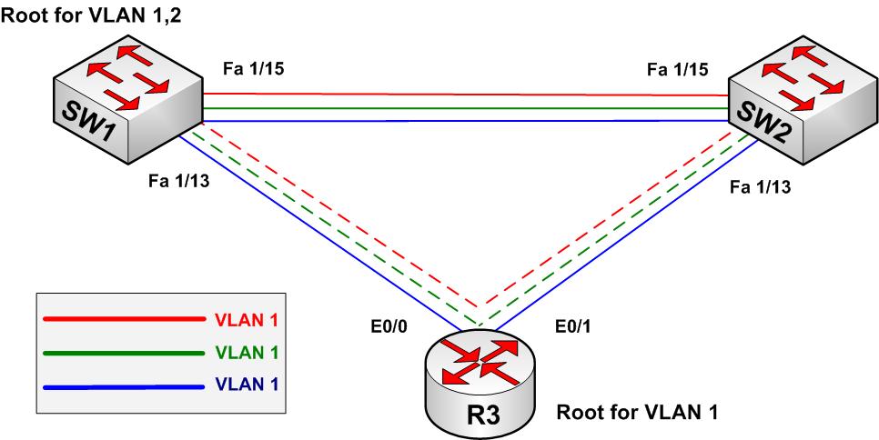
Consider the diagram below. SW1 and SW2 are Cisco switches, running STP instances for VLANs 1,2 and 3. Router R3 is converted into bridge (CRB mode and the same bridge-group on E0/0 and E0/1 interfaces, using IEEE STP protocol) to simulate an IEEE compatible switch. VLAN 1 STP instances of SW1 and SW2 are joined with STP instance running in R3. VLANs 2 and 3 consider path across R3 as another segment linking SW1 and SW2 and their SSTP information is passed transparently across R3.

The current situation in the topology is as following:
Rack1SW2#show spanning-tree vlan 1VLAN1 is executing the ieee compatible Spanning Tree protocol
Bridge Identifier has priority 32768, address cc07.00c1.0000
Configured hello time 2, max age 20, forward delay 15
Current root has priority 32768, address cc02.00c0.0000
Root port is 44 (FastEthernet1/3), cost of root path is 19
Topology change flag set, detected flag not set
Number of topology changes 12 last change occurred 00:00:39 ago
Times: hold 1, topology change 35, notification 2
hello 2, max age 20, forward delay 15
Timers: hello 0, topology change 0, notification 0, aging 300Port 44 (FastEthernet1/3) of VLAN1 is forwarding
Port path cost 19, Port priority 128, Port Identifier 128.44.
Designated root has priority 32768, address cc02.00c0.0000
Designated bridge has priority 32768, address cc02.00c0.0000
Designated port id is 128.5, designated path cost 0
Timers: message age 2, forward delay 0, hold 0
Number of transitions to forwarding state: 2
BPDU: sent 7650, received 2445Port 56 (FastEthernet1/15) of VLAN1 is blocking
Port path cost 19, Port priority 128, Port Identifier 128.56.
Designated root has priority 32768, address cc02.00c0.0000
Designated bridge has priority 32768, address cc06.00c0.0000
Designated port id is 128.56, designated path cost 19
Timers: message age 3, forward delay 0, hold 0
Number of transitions to forwarding state: 2
BPDU: sent 7, received 3827Rack1SW2#show spanning-tree vlan 2
VLAN2 is executing the ieee compatible Spanning Tree protocol
Bridge Identifier has priority 8192, address cc07.00c1.0006
Configured hello time 2, max age 20, forward delay 15
Current root has priority 8192, address cc06.00c0.0006
Root port is 44 (FastEthernet1/3), cost of root path is 19
Topology change flag set, detected flag not set
Number of topology changes 7 last change occurred 00:00:14 ago
from FastEthernet1/15
Times: hold 1, topology change 35, notification 2
hello 2, max age 20, forward delay 15
Timers: hello 0, topology change 0, notification 0, aging 300Port 44 (FastEthernet1/3) of VLAN2 is forwarding
Port path cost 19, Port priority 128, Port Identifier 128.44.
Designated root has priority 8192, address cc06.00c0.0006
Designated bridge has priority 8192, address cc06.00c0.0006
Designated port id is 128.44, designated path cost 0
Timers: message age 2, forward delay 0, hold 0
Number of transitions to forwarding state: 2
BPDU: sent 5889, received 372Port 56 (FastEthernet1/15) of VLAN2 is blocking
Port path cost 19, Port priority 128, Port Identifier 128.56.
Designated root has priority 8192, address cc06.00c0.0006
Designated bridge has priority 8192, address cc06.00c0.0006
Designated port id is 128.56, designated path cost 0
Timers: message age 2, forward delay 0, hold 0
Number of transitions to forwarding state: 1
BPDU: sent 2, received 3821Rack1SW2#show spanning-tree vlan 3
VLAN3 is executing the ieee compatible Spanning Tree protocol
Bridge Identifier has priority 32768, address cc07.00c1.0001
Configured hello time 2, max age 20, forward delay 15
Current root has priority 8192, address cc06.00c0.0007
Root port is 44 (FastEthernet1/3), cost of root path is 19
Topology change flag set, detected flag not set
Number of topology changes 4 last change occurred 00:00:16 ago
from FastEthernet1/15
Times: hold 1, topology change 35, notification 2
hello 2, max age 20, forward delay 15
Timers: hello 0, topology change 0, notification 0, aging 300Port 44 (FastEthernet1/3) of VLAN3 is forwarding
Port path cost 19, Port priority 128, Port Identifier 128.44.
Designated root has priority 8192, address cc06.00c0.0007
Designated bridge has priority 8192, address cc06.00c0.0007
Designated port id is 128.44, designated path cost 0
Timers: message age 1, forward delay 0, hold 0
Number of transitions to forwarding state: 2
BPDU: sent 3689, received 332Port 56 (FastEthernet1/15) of VLAN3 is blocking
Port path cost 19, Port priority 128, Port Identifier 128.56.
Designated root has priority 8192, address cc06.00c0.0007
Designated bridge has priority 8192, address cc06.00c0.0007
Designated port id is 128.56, designated path cost 0
Timers: message age 1, forward delay 0, hold 0
Number of transitions to forwarding state: 2
BPDU: sent 3, received 3832
R3 (the IEEE bridge) is the root for VLAN 1 (CST) and SW1 is the root for VLANs 2 and 3. Note that R3 has no idea about VLANs 2 and 3 and transparently floods SSTP BPDUs which could be seen on SW2 (non-root switch). As it should be, VLAN 1 BPDUs are received as IEEE STP BPDUs and SSTP copies are ignored.
Rack1SW2#debug spanning-tree bpdu
Spanning Tree BPDU debugging is on
Rack1SW2#
STP: VLAN1: config protocol = ieee, packet from FastEthernet1/3 , linktype IEEE_SPANNING , enctype 2, encsize 17
STP: enc 01 80 C2 00 00 00 CC 02 00 C0 00 01 00 26 42 42 03
STP: Data 00000000008000CC0200C00000000000008000CC0200C0000080050000140002000F00
STP: VLAN1 Fa1/3:0000 00 00 00 8000CC0200C00000 00000000 8000CC0200C00000 8005 0000 1400 0200 0F00STP: VLAN1: config protocol = ieee, packet from FastEthernet1/15 , linktype IEEE_SPANNING , enctype 2, encsize 17
STP: enc 01 80 C2 00 00 00 CC 06 00 C0 F1 0F 00 26 42 42 03
STP: Data 00000000008000CC0200C00000000000138000CC0600C0000080380100140002000F00
STP: VLAN1 Fa1/15:0000 00 00 00 8000CC0200C00000 00000013 8000CC0600C00000 8038 0100 1400 0200 0F00STP: VLAN3: config protocol = ieee, packet from FastEthernet1/3 , linktype SSTP , enctype 3, encsize 22
STP: enc 01 00 0C CC CC CD CC 06 00 C0 F1 03 00 32 AA AA 03 00 00 0C 01 0B
STP: Data 00000000002000CC0600C00007000000002000CC0600C00007802C0000140002000F00
STP: VLAN3 Fa1/3:0000 00 00 00 2000CC0600C00007 00000000 2000CC0600C00007 802C 0000 1400 0200 0F00STP: VLAN3: config protocol = ieee, packet from FastEthernet1/15 , linktype SSTP , enctype 3, encsize 22
STP: enc 01 00 0C CC CC CD CC 06 00 C0 F1 0F 00 32 AA AA 03 00 00 0C 01 0B
STP: Data 00000000002000CC0600C00007000000002000CC0600C0000780380000140002000F00
STP: VLAN3 Fa1/15:0000 00 00 00 2000CC0600C00007 00000000 2000CC0600C00007 8038 0000 1400 0200 0F00STP: VLAN2: config protocol = ieee, packet from FastEthernet1/3 , linktype SSTP , enctype 3, encsize 22
STP: enc 01 00 0C CC CC CD CC 06 00 C0 F1 03 00 32 AA AA 03 00 00 0C 01 0B
STP: Data 00000000002000CC0600C00006000000002000CC0600C00006802C0000140002000F00
STP: VLAN2 Fa1/3:0000 00 00 00 2000CC0600C00006 00000000 2000CC0600C00006 802C 0000 1400 0200 0F00
STP: VLAN2: config protocol = ieee, packet from FastEthernet1/15 , linktype SSTP , enctype 3, encsize 22
STP: enc 01 00 0C CC CC CD CC 06 00 C0 F1 0F 00 32 AA AA 03 00 00 0C 01 0B
Now let’s see how consistency checking is performed by PVST+.
Case 1: Change the native VLAN on SW1 connection to R3:
SW1:
interface FastEthernet 1/3
switchport trunk native vlan 2Rack1SW2#
%SPANTREE-2-RECV_PVID_ERR: Received BPDU with inconsistent peer vlan id 2 on FastEthernet1/3 VLAN1.%SPANTREE-2-BLOCK_PVID_PEER: Blocking FastEthernet1/3 on VLAN2. Inconsistent peer vlan.PVST+: restarted the forward delay timer for FastEthernet1/3
%SPANTREE-2-BLOCK_PVID_LOCAL: Blocking FastEthernet1/3 on VLAN1. Inconsistent local vlan.PVST+: restarted the forward delay timer for FastEthernet1/3
Note that SW2 detects untagged packet with VLAN ID 2, which does not correspond to the locally configured default native VLAN 1. The corresponding port is put in «inconsistent» state. The reason SW2 detects this condition (and not SW1) is because SW1 sending SSTP BPDUs and SW2 is not (it receives superios BPDUs). As soon as native VLAN is converted back to «1» on SW1, consistency is restored:
%SPANTREE-2-UNBLOCK_CONSIST_PORT: Unblocking FastEthernet1/3 on VLAN2. Port consistency restored.%SPANTREE-2-UNBLOCK_CONSIST_PORT: Unblocking FastEthernet1/3 on VLAN1. Port consistency restored. PVST+:Inconsistency timer expired. inconsistency 0
cleared for FastEthernet1/3
PVST+:Inconsistency timer expired. inconsistency 0
cleared for FastEthernet1/3
It is also possible to restore consistency by making VLAN 2 native on SW2 connection as well.
Case 2: Convert SW2 connection to R3 into an access-port in VLAN2:
SW2:
interface FastEthernet 1/3
switchport access vlan 2
switchport mode accessRack1SW2#
%SPANTREE-7-RECV_1Q_NON_TRUNK: Received 802.1Q BPDU on non trunk FastEthernet1/3 VLAN2.
%SPANTREE-7-BLOCK_PORT_TYPE: Blocking FastEthernet1/3 on VLAN2. Inconsistent port type.PVST+: restarted the forward delay timer for FastEthernet1/3
Now the access port receives untagged SSTP BPDUs from SW1 with VLAN ID TLV equal to 1. Since this does not match the locally configured VLAN, the port is declared «type-inconsistent» - the other side is trunk and the local side is an access port.
Note that it is still possible to configure the access port in VLAN1 if the other switch trunks are all using the default native VLAN. This way, only CST is expanded through the MST region and joined with VLAN1 STP instance in SW2. To summarize, if you have a group of Cisco switches connected to the same MSTP cloud (other vendor’s switches) observe the following rules:
1) Use the same interface types - i.e. either all switches are connected using access ports or using trunk ports.
2) Ensure Native VLAN (PVID) is the same on all trunks used to connect to an MST region.
Now let’s see the implications that arise from the fact that non-CST VLANs see the MST region as simply a link or a "hub". Based on that fact, it is possible to adjust priority values on not physically directly connected switches and influence root port election. For example, set the port priority of direct connection between SW1 and SW2 (port FastEthernet 1/15 to 64 (the default is 128):
SW1:
interface FastEthernet 1/15
spanning-tree port-priority 64Rack1SW2#show spanning-tree vlan 2
VLAN2 is executing the ieee compatible Spanning Tree protocol
Bridge Identifier has priority 8192, address cc07.00c1.0006
Configured hello time 2, max age 20, forward delay 15
Current root has priority 8192, address cc06.00c0.0006
Root port is 56 (FastEthernet1/15), cost of root path is 19
Topology change flag not set, detected flag not set
Number of topology changes 15 last change occurred 00:07:22 ago
from FastEthernet1/3
Times: hold 1, topology change 35, notification 2
hello 2, max age 20, forward delay 15
Timers: hello 0, topology change 0, notification 0, aging 300Port 44 (FastEthernet1/3) of VLAN2 is blocking
Port path cost 19, Port priority 128, Port Identifier 128.44.
Designated root has priority 8192, address cc06.00c0.0006
Designated bridge has priority 8192, address cc06.00c0.0006
Designated port id is 128.44, designated path cost 0
Timers: message age 1, forward delay 0, hold 0
Number of transitions to forwarding state: 0
BPDU: sent 0, received 8Port 56 (FastEthernet1/15) of VLAN2 is forwarding
Port path cost 19, Port priority 128, Port Identifier 128.56.
Designated root has priority 8192, address cc06.00c0.0006
Designated bridge has priority 8192, address cc06.00c0.0006
Designated port id is 64.56, designated path cost 0
Timers: message age 1, forward delay 0, hold 0
Number of transitions to forwarding state: 3
BPDU: sent 9, received 4683
Note that in above output, on both ports (root and alternative) we see the same designated bridge (SW1) – even though SW2 directly connects to R3 using port FastEthernet 1/3. Now let's make port Fa 1/3 of SW2 the root port by adjust the priority of port connecting SW1 to R3:
SW1:
interface FastEthernet 1/3
spanning-tree port-priority 32Rack1SW2#show spanning-tree vlan 3
VLAN3 is executing the ieee compatible Spanning Tree protocol
Bridge Identifier has priority 32768, address cc07.00c1.0001
Configured hello time 2, max age 20, forward delay 15
Current root has priority 8192, address cc06.00c0.0007
Root port is 44 (FastEthernet1/3), cost of root path is 19
Topology change flag set, detected flag not set
Number of topology changes 6 last change occurred 00:00:31 ago
from FastEthernet1/15
Times: hold 1, topology change 35, notification 2
hello 2, max age 20, forward delay 15
Timers: hello 0, topology change 0, notification 0, aging 300Port 44 (FastEthernet1/3) of VLAN3 is forwarding
Port path cost 19, Port priority 128, Port Identifier 128.44.
Designated root has priority 8192, address cc06.00c0.0007
Designated bridge has priority 8192, address cc06.00c0.0007
Designated port id is 32.44, designated path cost 0
Timers: message age 1, forward delay 0, hold 0
Number of transitions to forwarding state: 1
BPDU: sent 1, received 170Port 56 (FastEthernet1/15) of VLAN3 is blocking
Port path cost 19, Port priority 128, Port Identifier 128.56.
Designated root has priority 8192, address cc06.00c0.0007
Designated bridge has priority 8192, address cc06.00c0.0007
Designated port id is 64.56, designated path cost 0
Timers: message age 1, forward delay 0, hold 0
Number of transitions to forwarding state: 3
BPDU: sent 4, received 4850
To recap what has been said in a few words: PVST+ is used on 802.1q trunks to tunnel PVST instances across an MST cloud and build a CST consisting of PVST VLAN 1 and IEEE MST. PVST+ BPDUs contain special TLV with the source VLAN ID, which allows interconnected switches to detect inconsitencies or misconfigurations.
