MSTP Tutorial Part I: Inside a Region
Note: You may want to read a newer blog post on MSTP here Understanding MSTP
Before we begin with MSTP (Multiple Spanning Trees Protocol), I would like to note that this tutorial is going to be is divided in two parts. The first part describes how MSTP works inside a single region (the definition of the term will follow later). The second part is dedicated to MSTP region interaction with other regions and different STP protocols (IEEE STP, RSTP and Cisco PVST+).
Historical Review
First, a short history tour. In the beginning, there was IEEE STP protocol (originally, there also was DEC variant [the original] invented by Radia Perlman and IBM STP protocols, but those are fossils now), which was adapted for use with multiple VLANs and 802.1q trunks. A single shared tree, sometimes called Mono Spanning Tree by Cisco, or more often – Common Spanning Tree is shared by all VLANs. The obvious drawback of this design is impossibility to perform VLAN traffic engineering across redundant links: if a link is blocked, it is blocked for all VLANs. To overcome this, Cisco suggested its proprietary PVST/PVST+ solution, running a separate STP instance for each VLAN. This solution permits using different logical topology for each VLAN, effectively allowing for L2 traffic engineering. However, with the number of VLANs growing, PVST becomes a waste of switch resources and management burden, for the number of logical topologies is usually much smaller than the number of active VLANs.
As time passed, STP evolved into RSTP and Cisco answered with Rapid-PVST+: the fast STP, but with the same per-VLAN instance concept. The single spanning-tree instance used by IEEE and per-VLAN STP implemented by Cisco represents two poles in the space of possible solutions. Seeing the limitations of PVST approach, Cisco came with idea of decoupling the STP instance from a VLAN (they were bound together in PVST). The initial implementation was called MISTP (Multiple Instances Spanning Tree) and later evolved into new IEEE 802.1s standard called MSTP (Multiple Spanning Trees Protocol). As we would see later, this evolution process led to some terminology confusion, and small features mismatch between IEEE MSTP and Cisco MSTP implementation.
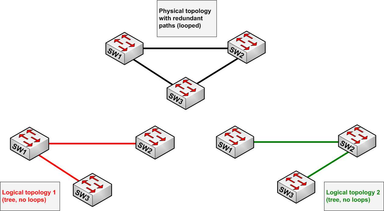
Logical and Physical Topologies
Look at the diagrams below:

Cisco’s original proposal was as follows. Instead of running an STP instance for each VLAN, let’s run a number of VLAN-independent STP instances (representing logical topologies) and then map each VLAN to the most appropriate logical topology (instance). Thus, the number of STP instances is kept to minimum (saving switch resources), but the network capacity is utilized in optimal fashion, by using all possible paths for VLAN traffic. The switch forwarding logic for VLAN traffic was changed a little bit. In order for a frame to be forwarded out of a port, two conditions must be met: first, VLAN must be active on this port (e.g. not filtered) and second, the STP instance the VLAN maps to, must be in non-discarding state for this port. Obviously, due to multiple logical topologies a single port could be blocking for one instance and forwarding for another (note that in (R)PVST+ a port is either forwarding or discarding for a VLAN).

Implementing MSTP
Now that the basic idea is understood, let’s think how it could be implemented. The following questions need to be answered:
- Topology Calculation. How to build multiple STP instances (logical topologies) in a single physical topology? Should we run multiple STP instances each with own BPDUs? If yes, then how would we distinguish every instance’s BPDUs: PVST+ uses VLAN tags for that, but now STP instances are independent of VLANs?
- Information Distribution.How to make all switches aware of VLAN to instance mappings? Should we distribute instance ID along with VLAN number? If yet, then how could we ensure all switches use consistent numbering?
- Consistency Check. How to ensure the above mapping is consistent across all switches? That is, would switch1 know that switch2 maps VLAN2 to the same instance 1 and not insance2?
Original Cisco MISTP pre-standard implementation sends separate BPDUs for each instance – this allows for separate STP calculations. Each BDPU contains instance number and a list of VLANs, mapped on sending switch to this particular instance – this allows for consistency check. However, the table to map VLANs to instance numbers has to be configured on each switch separately – that is, there is no automated mechanism to distribution VLAN to instance mappings. This is what Cisco did originally, but the IEEE 802.1s standard implementation made this mechanics more elegant. Before we continue discussing IEEE’s implementation, let’s define MSTP region as a collection of switches, sharing the same view of physical topology partitioning into set of logical topologies. For two switches to become members of the same region, the following attributes must match:
- Configuration name
- Configuration revision number (16 bits)
- The table of 4096 elements which map the respective VLAN to STP instance number
IEEE 802.1s implementation does not send a BDPU for each active STP instance, nor does it encapsulate VLAN list in each configuration message. Instead of that, a special STP instance number 0 called Internal Spanning Tree (IST or MSTI0) is designated to carry all “signaling” information. The BPDUs for IST contain all standard RSTP information for IST itself, as well as carry additional informational fields. Among others fields there are configuration name, revision number and a hash value computed over VLAN to STP instance mapping table contents. Using just this compact information it’s easy to detect misconfiguration on two neighboring switches.
What about other instances, besides the IST thing? Well, obviously, all VLANs could be mapped to IST – this is the default configuration. Effectively, this represents the case of classic IEEE RSTP with all VLANs sharing the same spanning-tree. Of course, other instances also exit, and they are called MSTIs – multiple spanning tree instances. Each MSTI may assign different priorities to switches, may have different link costs, port priorities and thus end up with it’s own logical topology. Now if the 802.1s standard implementation does not send separate BDPUs for each MSTI, how does it accomplish separate topologies? The MSTIs information is piggybacked into IST BPDUs in special MRecord fields (one for every active MSTI), which carries root priority, designated bridge priority, port priority and root path cost among others. Let’s see how this whole thing works.
First of all, since MSTP convergence mechanism stems from RSTP, there is no BDPU relaying process downstream from the root bridge. Every switch emits configuration BPDUs on it’s own, every Hello interval seconds. Every BDPU has full information about IST, and also MRecord for every MSTI . Using the RSTP convergence mechanics, separate STP instances are built for IST and every MSTI, using the information from IST BPDU and MRecords (root/designated bridge priorities, port priority, root path cost etc). Note that STP timers such as Hello, ForwardTime, MaxAge could only be tuned for IST, the instance 0. All other instances (MSTIs) inherit the timers from IST – this is the natural result of all MSTI information being piggybacked in IST BPDUs. Just as a side note, MSTP does not use MaxAge timer to age out old information, like RSTP/STP do. Instead of this, IST BDPUs has special field called MaxHops. IST root sends BPDUs with hop count equal to MaxHops and every other downstream switch decrements the hop count field on reception of IST BPDU. As soon as hop count becomes zero, the information in BPDU is ignored, and the switch may start declaring itself as new IST root. The old MaxAge/ForwardDelay timers are still used when MSTP interacts with RSTP, STP or (R)PVST+ bridges.
Caveats arising from VLAN/STP decoupling
Before we jump to configuration examples, let’s consider some issues, which may arise from the fact that spanning-tree instances now are not directly tied to VLANs. The general rule should be as following: “If a VLAN is active on a particular primary link (e.g. this link is non-backup in your logical topology), ensure the STP instance it maps to is forwarding on this link". Consider the following example:

In this topology, VLANs are manually pruned on trunks. Since the filtering is not consistent with the respective MSTI blocking decisions, VLAN2 traffic is blocked between SW1 and SW2. To avoid this situation, do not use “VLAN pruning” static method of distributing VLANs across trunks when you have MSTP enabled.
Another classic example, which may arise when you map VLANs to default IST:

Since there is just one STP instance, it blocks one of the ports. Unfortunately, this is the only port that VLAN3 can use. To avoid such situations, use separate STP for each logical topology (e.g. MSTI1 and MSTI2 in this case for VLAN2/VLAN3) and avoid mapping VLANs to IST. Keep IST only for information distribution, but load-balance traffic using MSTIs.
Configuration Example
Now that we have basic understanding of how MSTP works inside a region, let’s jump to the configuration stage. Consider the following physical topology already mentioned above:

The topology has VLANs 1, 10,20,30,40,50,60. We want to achieve the following:
1) VLANs 10,20,30 should follow uplink from SW3 to SW1
2) VLANs 40,50,60 should follow uplink from SW3 to SW2
3) If any of the uplinks fail, the respective VLANs should use the other uplink
To accomplish this, we need to create two MSTIs - let's give them numbers 1 and 2. SW1 will be the root for instance 1 and SW2 will be the root for instance 2. As for IST (MSTI0), let’s make SW3 the root switch for it (though it’s not recommended to assign root roles to access switches). VLAN 1 will remain mapped to IST, VLANs 10,20,30 to MSTI1, and VLANs 40,50,60 to MSTI2. Here is the configuration (pretty simple, inside a region):
SW1:
spanning-tree mode mst
!
spanning-tree mst configuration
name REGION1
instance 1 vlan 10, 20, 30
instance 2 vlan 40, 50, 60
!
spanning-tree mst 1 priority 8192
!
interface FastEthernet0/13
switchport trunk encapsulation dot1q
switchport mode trunk
!
interface FastEthernet0/16
switchport trunk encapsulation dot1q
switchport mode trunkSW2:
spanning-tree mst configuration
name REGION1
instance 1 vlan 10, 20, 30
instance 2 vlan 40, 50, 60
!
spanning-tree mst 2 priority 8192
!
interface FastEthernet0/13
switchport trunk encapsulation dot1q
switchport mode trunk
!
interface FastEthernet0/16
switchport trunk encapsulation dot1q
switchport mode trunkSW3:
spanning-tree mst configuration
name REGION1
instance 1 vlan 10, 20, 30
instance 2 vlan 40, 50, 60
!
spanning-tree mst 0 priority 8192
!
interface FastEthernet0/13
switchport trunk encapsulation dot1q
switchport mode trunk
!
interface FastEthernet0/16
switchport trunk encapsulation dot1q
switchport mode trunk
Let’s review the effect of our configuration.
SW1#show spanning-tree mst configuration
Name [REGION1]
Revision 0 Instances configured 3Instance Vlans mapped
-------- ---------------------------------------------------------------------
0 1-9,11-19,21-29,31-39,41-49,51-59,61-4094
1 10,20,30
2 40,50,60
-------------------------------------------------------------------------------
SW1#show spanning-tree mst##### MST0 vlans mapped: 1-9,11-19,21-29,31-39,41-49,51-59,61-4094
Bridge address 0019.5684.3700 priority 32768 (32768 sysid 0)
Root address 0012.d939.3700 priority 8192 (8192 sysid 0)
port Fa0/16 path cost 0
Regional Root address 0012.d939.3700 priority 8192 (8192 sysid 0)
internal cost 200000 rem hops 19
Operational hello time 2 , forward delay 15, max age 20, txholdcount 6
Configured hello time 2 , forward delay 15, max age 20, max hops 20Interface Role Sts Cost Prio.Nbr Type
---------------- ---- --- --------- -------- --------------------------------
Fa0/13 Desg FWD 200000 128.15 P2p
Fa0/16 Root FWD 200000 128.18 P2p##### MST1 vlans mapped: 10,20,30
Bridge address 0019.5684.3700 priority 8193 (8192 sysid 1)
Root this switch for MST1Interface Role Sts Cost Prio.Nbr Type
---------------- ---- --- --------- -------- --------------------------------
Fa0/13 Desg FWD 200000 128.15 P2p
Fa0/16 Desg FWD 200000 128.18 P2p##### MST2 vlans mapped: 40,50,60
Bridge address 0019.5684.3700 priority 32770 (32768 sysid 2)
Root address 001e.bdaa.ba80 priority 8194 (8192 sysid 2)
port Fa0/13 cost 200000 rem hops 19Interface Role Sts Cost Prio.Nbr Type
---------------- ---- --- --------- -------- --------------------------------
Fa0/13 Root FWD 200000 128.15 P2p
Fa0/16 Altn BLK 200000 128.18 P2pSW1#show spanning-tree mst interface fastEthernet 0/13
FastEthernet0/13 of MST0 is designated forwarding
Edge port: no (default) port guard : none (default)
Link type: point-to-point (auto) bpdu filter: disable (default)
Boundary : internal bpdu guard : disable (default)
Bpdus sent 561, received 544Instance Role Sts Cost Prio.Nbr Vlans mapped
-------- ---- --- --------- -------- -------------------------------
0 Desg FWD 200000 128.15 1-9,11-19,21-29,31-39,41-49,51-59
61-4094
1 Desg FWD 200000 128.15 10,20,30
2 Root FWD 200000 128.15 40,50,60SW1#show spanning-tree mst interface fastEthernet 0/16
FastEthernet0/16 of MST0 is root forwarding
Edge port: no (default) port guard : none (default)
Link type: point-to-point (auto) bpdu filter: disable (default)
Boundary : internal bpdu guard : disable (default)
Bpdus sent 550, received 1099Instance Role Sts Cost Prio.Nbr Vlans mapped
-------- ---- --- --------- -------- -------------------------------
0 Root FWD 200000 128.18 1-9,11-19,21-29,31-39,41-49,51-59
61-4094
1 Desg FWD 200000 128.18 10,20,30
2 Altn BLK 200000 128.18 40,50,60
Note a few things here. The cost values are much higher than the default STP costs, and MSTIx is called MSTx (e.g. IST is MST0). Aside from that, note the term “Regional Root” which is to be explained in details in Part 2. As for this part, you can see that configuration MSTP inside a region is pretty simple. You just need to execute some caution, when filtering and mapping VLANs, but if you plan logical topologies in advance this should not cause any problems.
