MSTP Tutorial Part II: Outside a Region
Note: You may want to read a newer blog post on MSTP here Understanding MSTP
This post continues the previous article dedicated to MSTP operations inside a single region. Before reading any further, make sure you read and fully understand the first part of MSTP overview: MSTP Tutorial Part I: Inside a Region. The information there is critical to understand the new post.
The concept of CIST
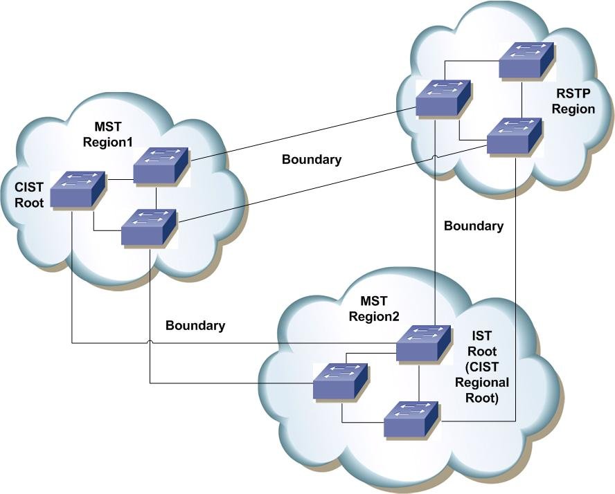
As you remember, every MSTP region runs special instance of spanning-tree known as IST or Internal Spanning Tree (=MSTI0). This instance is active on all links inside a region and serves the purpose of disseminating STP topology information for other STP instances. As usual, IST has a root bridge, elected based on the lowest bridge ID (priority/MAC address). However, situation changes when you have different regions in the network (e.g. switches with different region names, different revisions, etc). When a switch detects BPDU messages sourced from another region on any link, it marks the link as MSTP boundary. On the figure below you can see two MSTP regions connected via two separate links (disregard the RSTP region for now).

Now two regions should build a common spanning tree known as CIST – Common and Internal Spanning Tree. This tree is result of joining ISTs of each region in a special manner. Here is a detailed description of the process.
1) In addition to sending IST configuration BPDUs, every switch initially declares itself as the root of CIST. The switches pass CIST configuration information along with IST information in additional BPDU fields. Switches inside a region never change the path cost to the CIST Root, known as CIST External Root Path Cost. Instead of that, the external path cost only changes on the boundary ports. Thus, this external cost only accounts for the cost of boundary links, not the cost of the paths inside a region. Essentially, CIST External Path Cost information “tunnels” across a region.
2) On boundary ports, switches exchange their CIST BPDU information ONLY. That is, switches hide IST information between regions, but pass CIST metrics. The usual RSTP synchronization process takes places between switches on a border link, and eventually ONE switch with the lowest BID (Bridge ID = Priority + MAC Address) among all regions is elected as the CIST Root. Note that each region still elects a local IST root, known as CIST Regional Root, as described further.
3) The region that contains the CIST Root, declares this switch as the root of local IST as well. However, things start to differ for regions that don’t contain the CIST root. All of them elect one of the border switches (switches connected to other regions) as IST root (aka CIST Regional Root). This procedure elects the IST Root (CIST Regional Root) based on the lowest CIST External Root Path Cost. Note that this procedure differs from elections based purely on BID, which take place inside a single region. In this case, the procedure uses BIDs as tiebreaker, if two or more switches have the same CIST Root External Path Cost. MSTP blocks all redundant boundary “uplinks” marking them as “alternate” paths to the CIST Root. The boundary switches do so by receiving “extra” CIST BPDUs on top of IST BPDUs with external root path cost values and comparing them with the ones received on local boundary ports.
4) Inside a region, switches build regular IST, using the CIST Regional Root as the root of IST. Note that this tree uses so-called Internal Root Path Cost stored in the local IST BPDUs. This cost increments along all the links inside a region, but it never leaks out of the region. Between regions, switches exchange information about CIST External Root Path cost only.

Note that switch with non-optimal priority value may become the CIST Regional Root (local IST Root). For example, if you configure a switch inside a region with a lowest BID among all switches it may not necessarily become the CIST Regional Root. Only if the switch has the lowest BID among all regions it would be elected as CIST Root.
The concept of CST and STP interoperation
From the above information, we conclude that CIST essentially has organization of a two-level hierarchy. The first level treats all regions as “pseudo-bridges” and operates with the External Root Path Cost. The first-level spanning tree roots in CIST Root Bridge and encompasses the pseudo-bridges. They call it CST or Common Spanning Tree. Effectively, this has no idea of the internal MSTP regions structure, but sees each region as a virtual bridge.

This is the point where MSTP interoperates with legacy IEEE STP/RSTP regions as well. The legacy switch regions have no concept of IST, so they simply join their STP instance with the CST and perceive MSTP regions as “transparent” pseudo-bridges, staying unaware of their internal topology. (Note that it may happen so that a switch with the lowest BID belongs to RSTP/STP region. This situation results in all MSTP regions electing local CIST Regional Roots and considering the new CIST Root located outside MSTP “domain”). Naturally, MSTP detects the appropriate STP version on a boundary link and switches to the respective mode of operations (e.g. RSTP/STP).
The second level of CIST hierarchy consists of various regional ISTs. Every MSTP region builds IST instance using the internal path costs and following the optimal “internal” topology. As you remember, this “internal topology” transparently transports the “external” BPDU information to the border switches, so that they can elect Regional CIST Root. The fist level topology (CST) is somewhat independent of the second level topology (IST) and bases upon the CIST root and cost of the boundary links. The second level topology (“internal”, IST) may change in case if boundary link cost changes or something happens to the CIST Root, since this affect the election of the Regional CIST Root.
MSTP pseudo-bridges do not strictly emulate the real bridges. For example, different boundary switches send their own BID in BPDUs, so the pseudo-bridge may appear to have many BIDs on various boundary links. However, this has no impact on the process of transparent tunneling of CIST Root information across the pseudo-bridge. Other things that don’t see pseudo-bridge as non-transparent include MSTP hop count or MaxAge timer value, for they may change asynchronously, as information travels along different paths inside a region.
MSTIs and CIST
Now, what could be said about the MSTIs – individual STP instances used inside regions? From what we learned so far, it is easy to conclude that the only logical solution is to map all MSTP instances to the CIST on the boundary links. This implies that you cannot load-balance VLAN traffic on the boundary links by mapping VLANs to different instances. All VLANs use the same non-blocking uplink that CIST elected as the optimal path to the CIST Root. But this only applies to the "CST" paths connecting the regional virtual bridges - inside any region VLANs follow the internal topology paths, based on the respective MSTI configurations.
It is important to note that MSTIs have no idea of the CIST Root whatsoever; they only use internal paths and internal MSTI root to build the spanning tree. However, all MSTP instances see the root port (towards the CIST Root) of the CIST Regional Bridge as the special “Master Port” connecting them to the “outside” world. This port serves the purpose of the “gateway” linking MSTI's to other regions. Notice that switches do not send M-records (MSTI information) out of boundary ports, only CIST information and thus . Thus, the CIST and MSTI's may converge independently and in parallel. The master port will ony beging forwarding when all respective MSTI ports are in sync and forwarding to avoid temporary bridging loops.
MSTP and Fault Isolation
Ethernet is known for its broadcast nature that tends propagating issues across the whole Layer 2 domain. There are tree main problems with Ethernet that affect MSTP designs:
- Unknown unicast flooding results in traffic surges under topology changes. Every topology change may cause massive invalidation of MAC address tables and unicast traffic flooding. This process is the result of Ethernet topology unawareness – the bridges don’t know MAC addresses location.
- Broadcas and Multicast flooding. This is a separate problem as many core protocols (ARP, IGP, PIM) rely on multicasting or broadcasting. Thos packets should be delivered to every node in a broadcast domain and under intense load network could be congested at every point.
- Spanning-Tree Convergence. MSTP uses RSTP procedure for STP re-negotiation. Since it is based on distance-vector behavior, it is prone to convergence issue, such as counting to infinity (old information circulation). This is especially noticeable in larger topologies with 10 switches and more and under special conditions, such as failure of the root bridge.
The concept of MSTP region allows for bounding STP re-computations. Since MSTIs in every region are independent, any change affecting MSTI in one region will not affect MSTIs in other regions. This is a direct result of the fact that M-record information is not exchanged between the regions. However, CIST recalculations affect every region and might be slow converging. This is why it is a good idea not to map any VLAN to CIST.
Topology changes in MSTP are treated the same way as in RSTP. That is, only non-edge links going to forwarding state will cause a topology change. A single physical link may be forwarding for one MSTI and blocking for another. Thus, a single physical change may have different effect on MSTIs and the CIST. Topology changes in MSTIs are bounded to a single region, while topology changes to the CIST propagate through all regions. Every region treats the TC notification from another region as “external” and applies them to CIST-associated ports only.
A topology change to CST (the tree connecting the virtual bridges) will affect all MSTIs in all regions and the CIST. This is due to the fact that new link becoming forwarding between the virtual bridges may change all paths in the topology and thus require massive MAC address re-learning. Thus, from the standpoint of topology change, something happening to the CST will have most massive impact of flooding in the set of interconnected MSTP regions.
The above observations advise a good design rule for MSTP networks – separated “meshy” topologies in their own regions and interconnect regions using “sparse” mesh, keeping in mind balance between redundancy and topology changes effect. This is an adaptation of well-know design principle - separate complexity from complexity to keep networks more stable and isolate fault domains.
Interoperating with PVST+
This task poses a tough issue. We know that PSVST+ runs an STP instance for every VLAN. On a contrary, MSTP maps VLANs to MSTIs, so one-to-one mapping between VLAN and STP instance no longer holds true. How should an MSTP switch operate on a border link connected to the PVST+ domain? As we remember, on the border with IEEE STP domain, PVST+ simply joins VLAN 1 STP with IEEE STP and tunnels SSTP BPDUs across the IEEE STP domain (refer to PVST+ Explained article for more information).
However, MSTP runs multiple MSTIs inside a region and maps them all to CIST on the border link. That means we need to make sure that internal MSTIs could be aware of changes in PVST+ trees. It’s hard to automatically map VLAN-based STPs to MSTI and so the simplest way to accomplish the desired behavior is to join all PVST+ trees with CIST. This way, changes in any of PVST+ STP instances propagate to CIST/IST and affect all MSTIs in result. While not the optimal solution, it ensure that no changes go unnoticed and no black holes occur in a single VLAN due to the topology changes.
The MSTP implementation simulates PVST+ by replicating CIST BPDUs on the link facing the PVST+ domain and sending the BPDUs on ALL VLANs active on the trunk. The MSTP switch consumes all BDPUs received from PVST+ domain and processes them using the CIST/IST instance. The PSVT+ side sees the MSTP domain as a special PVST+ domain with all per-VLAN instances claiming the CIST Root as the root of their STP. Note that PVST+ also interprets the whole region as a single pseudo-bridge, but operating in PSVT+ mode. The two possible options are allowed here:
1) MSTP domain (either a single region or multiple regions) contains the root bridge for ALL VLANs. This is only true if CIST Root BID is better than any PVST+ STP root BID. This is the preferred design, for you can manipulate uplink costs on the PVST+ side and obtain optimal traffic engineering results.
2) PVST+ contains the root bridges for ALL VLANs, including VLAN1, which maps to CST of STP. This is only true is all PVST+ root bridges BIDs for all VLANs are better than CIST Root BID. This is not the preferred design, since all MSTIs map to CIST on the border link, and you cannot load-balance the MSTIs as the enter the PVST+ domain.
Cisco implementation does not support the second option. MSTP domain should contain the bridge with the best BID, to ensure that the CIST Root is also the root for all PVST+ trees. If any other case, MSTP border switch will complain and place the ports that receive superior BPDUs from PVST+ region in root-inconsistent state. To fix this issue, ensure that PVST+ domain does not have any bridges with BIDs better than the CIST Root Bridge ID.
Scenario 1: CIST Root and CIST Regional Root
In this scenario, we configure four switches in two regions. The first region consists of one switch (SW1) and the second region consists of three switches: SW2, SW3 and SW4. SW1 is the CIST root thanks to its lowest priority. SW2 is the CIST Regional Root. We also demonstrate some path manipulation options.

SW1:
spanning-tree mode mst
spanning-tree mst 0 priority 4096
!
spanning-tree mst configuration
name REGION1
exitSW2:
spanning-tree mode mst
spanning-tree mst configuration
name REGION234
exit
!
interface range FastEthernet 0/13 - 14
spanning-tree mst 0 cost 100SW3:
spanning-tree mode mst
spanning-tree mst configuration
name REGION234
exit
!
interface FastEthernet 0/19
spanning-tree mst 0 cost 100SW4:
spanning-tree mode mst
spanning-tree mst configuration
name REGION234
exit
spanning-tree mst 0 priority 16384
!
interface FastEthernet 0/16
spanning-tree mst 0 cost 100
In the above configuration we adjusted some link costs to ensure that
1) MSTP elects SW2 as the CIST Regional root due to its shortest path to the CIST Root. SW2 is the CIST Regional Root for REGION234, even though SW4 has better switch priority.
2) SW3 selects the path through SW4 to reach internal root bridge due to the shortest path cost via SW4.
Verifications:
SW2#show spanning-tree mst 0##### MST0 vlans mapped: 1-4094
Bridge address 0019.564c.c580 priority 32768 (32768 sysid 0)
Root address 0019.55e6.d380 priority 4096 (4096 sysid 0)
port Fa0/13 path cost 100
Regional Root this switch
Operational hello time 2 , forward delay 15, max age 20, txholdcount 6
Configured hello time 2 , forward delay 15, max age 20, max hops 20Interface Role Sts Cost Prio.Nbr Type
---------------- ---- --- --------- -------- --------------------------------
Fa0/13 Root FWD 100 128.15 P2p Bound(RSTP)
Fa0/14 Altn BLK 100 128.16 P2p Bound(RSTP)
Fa0/16 Desg FWD 200000 128.18 P2p
Fa0/19 Desg FWD 200000 128.21 P2p
Note the following: SW2 is the Root Bridge (CIST Root) with priority 4096. The root port is Fa 0/13, elected based on regular STP rules (shortest path, lowest upstream port priority). The other uplink is blocking. Both ports show up as “Boundary” since they face the other MSTP domain. Note that SW2 is the Regional Root due to the fact that is has the shortest path to the CIST Root.
Now look at SW4. This switch has lower priority than SW2, but it is not elected as the CIST Regional Root, for SW4 path cost to the CIST Root is worse
SW4#show spanning-tree mst 0##### MST0 vlans mapped: 1-4094
Bridge address 000b.5f02.1100 priority 16384 (16384 sysid 0)
Root address 0019.55e6.d380 priority 4096 (4096 sysid 0)
port Fa0/16 path cost 100
Regional Root address 0019.564c.c580 priority 32768 (32768 sysid 0)
internal cost 100 rem hops 19
Operational hello time 2 , forward delay 15, max age 20, txholdcount 6
Configured hello time 2 , forward delay 15, max age 20, max hops 20Interface Role Sts Cost Prio.Nbr Type
---------------- ---- --- --------- -------- --------------------------------
Fa0/13 Altn BLK 200000 128.13 P2p Bound(RSTP)
Fa0/16 Root FWD 100 128.16 P2p
Fa0/19 Desg FWD 200000 128.19 P2p
Note the following in the above output. First, the local switch has priority value of 16834 and the CIST Root has priority value of 4096. Next the path cost to CIST Root is 100 – the same value that SW2 (the CIST Regional Root) has. This is a direct consequence from the fact that CIST External Root Path cost never increments along the internal paths. The CIST Regional Root is SW2 with the default priority, and the internal path cost is 100 – just as we set it. The boundary port is Fa 0/13 and it is blocking (we are not the CIST Regional Root). The port connected to SW2 is out root port (internal root port). Finally inspect the show output on SW3:
SW3#show spanning-tree mst 0##### MST0 vlans mapped: 1-4094
Bridge address 000d.bd27.de00 priority 32768 (32768 sysid 0)
Root address 0019.55e6.d380 priority 4096 (4096 sysid 0)
port Fa0/19 path cost 100
Regional Root address 0019.564c.c580 priority 32768 (32768 sysid 0)
internal cost 200 rem hops 18
Operational hello time 2 , forward delay 15, max age 20, txholdcount 6
Configured hello time 2 , forward delay 15, max age 20, max hops 20Interface Role Sts Cost Prio.Nbr Type
---------------- ---- --- --------- -------- --------------------------------
Fa0/16 Altn BLK 200000 128.16 P2p
Fa0/19 Root FWD 100 128.19 P2p
Again, we see that SW1 is the CIST Root with the External Root Path Cost of 100 (it never changes inside the region). SW2 is the CIST Regional Root with the internal path cost of 200 (across SW4). The link to SW2 is the root port of SW4.
Scenario 2: MSTIs and the Master Port
In this scenario we adds another STP instance to REGION234. We also add two VLANs 10 and 20 to all switches and map them to MSTI 1 in REGION234.
SW1:
vlan 10,20SW2, SW3 & SW4:
vlan 10,20
!
spanning-tree mst configuration
instance 1 vlan 10, 20
Let’s see the show command output in SW2.
SW2#show spanning-tree mst 1##### MST1 vlans mapped: 10,20
Bridge address 0019.564c.c580 priority 32769 (32768 sysid 1)
Root address 000b.5f02.1100 priority 32769 (32768 sysid 1)
port Fa0/19 cost 200000 rem hops 19Interface Role Sts Cost Prio.Nbr Type
---------------- ---- --- --------- -------- --------------------------------
Fa0/13 Mstr FWD 200000 128.15 P2p Bound(RSTP)
Fa0/14 Altn BLK 200000 128.16 P2p Bound(RSTP)
Fa0/16 Altn BLK 200000 128.18 P2p
Fa0/19 Root FWD 200000 128.21 P2p
There is no Regional Root here. Just regular root, which is the root of MSTI, elected using the regular STP rules. In our case, the root is SW4 and the root port is Fa 0/19. Next note the special “Master Port”. This is the uplink port of CIST Regional Root. All MSTIs map to CIST here, and follow the single path. This port is also forwarding and provides the path upstream to the CIST Root for all MSTIs and their VLANs.
Scenario 3: PVST+ and MSTP interoperation
In this scenario, we configure SW1 to use PSVT+ and see how it interworks with MSTP. First, configure so that SW1 is the root bridge for all VLANs and that it beats all bridges in MSTP domain.
SW1:

spanning-tree mode pvst

spanning-tree vlan 1-4094 priority 8192
Let’s see what happens on SW2:
%SPANTREE-2-PVSTSIM_FAIL: Superior PVST BPDU received on VLANSW2#show spanning-tree mst 0
##### MST0 vlans mapped: 1-9,11-19,21-4094
Bridge address 0019.564c.c580 priority 32768 (32768 sysid 0)
Root address 0019.55e6.d380 priority 4097 (4096 sysid 1)
port Fa0/13 path cost 100
Regional Root this switch
Operational hello time 2 , forward delay 15, max age 20, txholdcount 6
Configured hello time 2 , forward delay 15, max age 20, max hops 20Interface Role Sts Cost Prio.Nbr Type
---------------- ---- --- --------- -------- --------------------------------
Fa0/13 Root BKN*100 128.15 P2p Bound(PVST) *PVST_Inc
Fa0/14 Altn BLK 100 128.16 P2p Bound(PVST)
Fa0/16 Desg FWD 200000 128.18 P2p
Fa0/19 Desg FWD 200000 128.21 P2p
First note the syslog message in the beginning. It says that while emulating PVST+ the MSTP code encountered the situation where PVST+ domain claims itself as a root for one or more VLANs. This implies PVST+ bridge having better BID than the current CIST Root. As a result, even though the MSTP considers the new root as the “legitimate” new CIST Root, it blocks the uplink port as PVST Simulation Inconsistent. This process results in interesting situation – even though the PVST+ domain contains the CIST Root, the MSTP domain cannot reach it. In effect, potential loops are eliminated, but the MSTP domain loses connectivity to the PVST+ domain. The same situation could be observed with the MSTI 1:
SW2#show spanning-tree mst 1##### MST1 vlans mapped: 10,20
Bridge address 0019.564c.c580 priority 32769 (32768 sysid 1)
Root address 000b.5f02.1100 priority 32769 (32768 sysid 1)
port Fa0/19 cost 200000 rem hops 19Interface Role Sts Cost Prio.Nbr Type
---------------- ---- --- --------- -------- --------------------------------
Fa0/13 Mstr BKN*200000 128.15 P2p Bound(PVST) *PVST_Inc
Fa0/14 Altn BLK 200000 128.16 P2p Bound(PVST)
Fa0/16 Altn BLK 200000 128.18 P2p
Fa0/19 Root FWD 200000 128.21 P2p
Here we see that the “Master Port” is blocked due to the PSVT simulation inconsistency. To resolve this issue you need to ensure that MSTP domain contains the root bridge for all PVST+ trees. This is accomplished by tuning priority value for IST to a number lower than any PVST+ bridge priority.
SW1:
spanning-tree mode pvst
spanning-tree vlan 1-4094 priority 8192SW2:
spanning-tree mst 0 priority 4096
Now SW2 is the new CIST Root. Look at the show command output now:
SW2#show spanning-tree mst 0##### MST0 vlans mapped: 1-9,11-19,21-4094
Bridge address 0019.564c.c580 priority 4096 (4096 sysid 0)
Root this switch for the CIST
Operational hello time 2 , forward delay 15, max age 20, txholdcount 6
Configured hello time 2 , forward delay 15, max age 20, max hops 20Interface Role Sts Cost Prio.Nbr Type
---------------- ---- --- --------- -------- --------------------------------
Fa0/13 Desg LRN 100 128.15 P2p Bound(PVST)
Fa0/14 Desg BLK 100 128.16 P2p Bound(PVST)
Fa0/16 Desg FWD 200000 128.18 P2p
Fa0/19 Desg FWD 200000 128.21 P2pSW2#show spanning-tree mst 1
##### MST1 vlans mapped: 10,20
Bridge address 0019.564c.c580 priority 32769 (32768 sysid 1)
Root address 000b.5f02.1100 priority 32769 (32768 sysid 1)
port Fa0/19 cost 200000 rem hops 19Interface Role Sts Cost Prio.Nbr Type
---------------- ---- --- --------- -------- --------------------------------
Fa0/13 Desg FWD 200000 128.15 P2p Bound(PVST)
Fa0/14 Desg FWD 200000 128.16 P2p Bound(PVST)
Fa0/16 Altn BLK 200000 128.18 P2p
Fa0/19 Root FWD 200000 128.21 P2p
All SW2 ports are now designated. It correctly emulates the PVST+ interactions, and SW1 sees SW2 as the root of all PVST+ instances. SW1 will then block one of its redundant uplink based on the regular STP rules. In this situation, traffic may flow between the PVST+ and MSTP domains and you can achieve optimal load-balancing using the PSVT+ cost tuning on SW1.
