CCENT Basic Serial Interface Connectivity
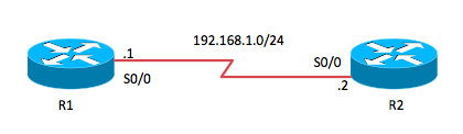
In this post, we will examine the steps required to ensure full reachability over a Serial interface between two Cisco routers. Here is the network diagram that presents the topology used in this scenario:

When we are in a lab environment, we can simulate a wide area connection (WAN) between two routers using a simple crossover cable designed for our router interfaces. One end of the cable is the DTE (Data Terminal Equipment), and the other is the DCE (Data Circuit-terminating Equipment). The DTE end synchronizes the connection to the clock rate of the link that is provided by the DCE. Notice that C does not stand for Clock in DCE, but it is a nice way to remember what that function does! Think of the clock on the line like a metronome, setting the "tempo" of communications.
For our first task, we want to determine which router has the DCE connection. We will use the show controllers serial 0/0 command to do this.
R2>enable

R2#show controllers serial 0/0

Interface Serial0/0

Hardware is GT96K

DCE 530, clock rate 2000000

idb at 0x652EE7AC, driver data structure at 0x652F5ED0

wic_info 0x652F64D4

Physical Port 1, SCC Num 1

MPSC Registers:

...
The R2 device has the DCE end connected as we can see in the output from this command. Notice there is a bunch of output from this command we do not need, so I omitted it here in the blog.
Now that we know which interface is which, we are ready to begin configurations. I will start right here on R2 for convenience. Because it is the DCE interface, I will set the clock rate, the bandwidth for the interface, and set the IP address. I want to use PPP (Point-to-Point Protocol), often jokingly called the Planet's Most Popular Protocol, so I will set that on the interface as well. The default protocol for a Serial link in Cisco networking is Cisco's version of HDLC (High-Level Data Link Control). Finally, I will enable the interface with the no shutdown command.
Please note that the bandwidth command is not actually setting the bandwidth, it is responsible for "reporting" the bandwidth to processes like routing protocols.
R2#

R2#configure terminal

Enter configuration commands, one per line.  End with CNTL/Z.

R2(config)#interface serial0/0

R2(config-if)#clock rate 64000

R2(config-if)#bandwidth 64

R2(config-if)#ip address 192.168.1.2 255.255.255.0

R2(config-if)#encapsulation ppp

R2(config-if)#no shutdown

R2(config-if)#end

R2#

*Mar  1 02:20:51.291: %LINK-3-UPDOWN: Interface Serial0/0, changed state to up

*Mar  1 02:20:51.615: %SYS-5-CONFIG_I: Configured from console by console

R2#
Notice when I set the clock rate I set a real slow speed (64 Kbps). This is to ensure that the interfaces can easily support it in my lab environment. You should also notice the status message received after the configuration. The interface has come up at Layer 1, but has no chance to come up at Layer 2, as we are sure to have an encapsulation mismatch with the other end of the link (running the default HDLC).
Now it is time to configure R1. Notice it is very nearly a mirror of the configuration, the only difference is the IP address and the lack of the clock rate command.
Also, notice the verification steps. We see Layer 1 and Layer 2 come up, and we can ping the far side link IP address.
R1>enable

R1#configure terminal

Enter configuration commands, one per line.  End with CNTL/Z.

R1(config)#interface serial 0/0

R1(config-if)#bandwidth 64

R1(config-if)#ip address 192.168.1.1 255.255.255.0

R1(config-if)#encapsulation ppp

R1(config-if)#no shutdown

R1(config-if)#end

R1#

*Mar  1 02:22:26.343: %LINK-3-UPDOWN: Interface Serial0/0, changed state to up

*Mar  1 02:22:27.031: %SYS-5-CONFIG_I: Configured from console by console

*Mar  1 02:22:27.375: %LINEPROTO-5-UPDOWN: Line protocol on Interface Serial0/0, changed state to up

R1#ping 192.168.1.2

Type escape sequence to abort.

Sending 5, 100-byte ICMP Echos to 192.168.1.2, timeout is 2 seconds:

!!!!!

Success rate is 100 percent (5/5), round-trip min/avg/max = 4/8/20 ms

R1#
Thanks for reading and enjoy your studies!
