DMVPN Phase 3: Overview & Configuration
In this post we are going to speak mainly of NHRP. The other important part of DMVPN - IPsec - is relatively the same, and did not change with introduction of NHRP Phase 3. To begin with, let's quickly recall the core features of NHRP Phase 1 & 2. For detailed overview, you may refer to DMVPN Explained
NHRP Phase 1:
No spoke-to-spoke tunnels but spokes dynamically register their NBMA addresses with the hub. Spokes use p2p tunnels and route all traffic across the hub. It is OK to summarize routes on the hub router and limit the amount of routing information received by the spokes.
NHRP Phase 2:
Uses a special CEF “trick” to implement spoke2spoke tunnels. All spokes need to receive full routing information with next-hop unchanged (e.g. using no next-hop-self eigrp or OSPF broadcast network type).
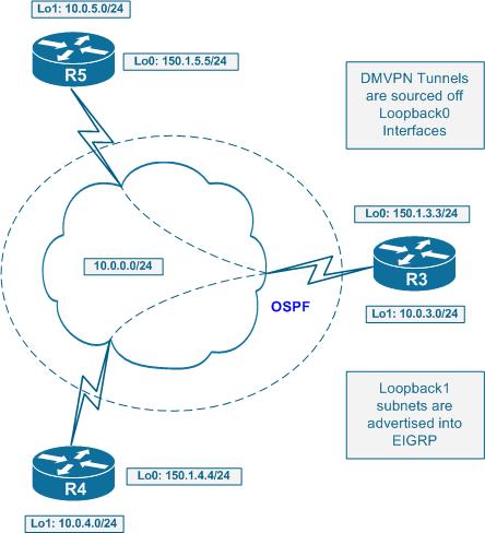
Look at the following topology:

For example spoke R5 will receive route 10.0.4.0/24 with the next hop of 10.0.0.4 even though the route has been “relayed” via the hub. This allows for installation of a special CEF entry for 10.0.4.0/24 with the next hop set to 10.0.0.4 and marked as “invalid”. At the same time, the CEF adjacency for 10.0.0.4 is marked as “glean” meaning it needs L3 to L2 lookup to be performed. This L3->L2 lookup is performed by NHRP, when an initial packet is being sent to 10.0.4.0/24.
An example of incomplete CEF entry with NHRP Phase 2:Rack1R5#show ip cef 10.0.4.0
10.0.4.0/24, version 48, epoch 0
0 packets, 0 bytes
via 10.0.0.4, Tunnel0, 0 dependencies
next hop 10.0.0.4, Tunnel0
invalid adjacencyRack1R5#show ip cef 10.0.0.4
10.0.0.0/24, version 50, epoch 0, attached, connected
0 packets, 0 bytes
via Tunnel0, 0 dependencies
valid glean adjacency
The initial packet is routed using process switching across the hub. The resolution trigger forces the originating router to send out an NHRP resolution request, which travels to the NHS that responds with known information and allows the spoke to complete the CEF entry.
The critical element of NHRP Phase 2 is preservation of the reachability information, via unmodified next-hop IP address. This implies every spoke must receive the full routing tables (no summarization!) of all other spokes in order to be able to establish spoke2spoke tunnels. This limits the scalability in large networks. Plus, the initial packet should be process switched, as the CEF entry is not complete in the beginning.
However, the worst problem is that next-hop issue. It limits the DMVPN topologies by only allowing one level of hubs. You may use multiple hubs to improve scalability - like one hub servicing half of your spokes and another servicing the other half. But you are forced to link them in daisy-chain as NHS servers of each other. This is needed to allow the NHRP resolution requests to traverse all potential NHS servers. The static linking reduces overall reliability.
The root of all evils with NHRP Phase 2 is that the hub is the only source of NHRP information, as all spokes register their Tunnel/NBMA IP addresses with it. Since the “glean” adjacency is only for the next-hop, the spokes never ask about anything else in their NHRP requests.
NHRP Phase 3
NRHP Phase 3 involves spokes in responding to NHRP resolution requests. Thus, the unique role of hub as the only source of NHRP information is reduced. Let's look at NHRP Phase 3 work.
Step 1:
Spokes register their Tunnel/NBMA mappings with the hub (or hubs). This allows the hub to dynamically discover all spokes and establish routing adjacencies. After this, the routing information is exchanged. However, now the hub is not required to preserve the reachability information - you can summarize information as it's being send down to the spokes. You can even go as far as simply sending a default route to all spokes. This greatly improves network scalability.
Step 2:
As the spokes receive routing information, they populate their CEF tables. There are no more invalid or glean adjacencies - all of them are complete. Naturally, they all point to the NBMA IP address of the hub router. Thus, initially, all spoke2spoke packets are CEF switched across the hub. But this also means that the invalid CEF entries no longer trigger the NHRP resolution requests! So how does the spoke learn about true NBMA IP address of the target network? This all thanks to NHRP redirect message.
Step 3:
Let's say an mGRE tunnel is configured for NHRP redirects (the first magic component of NHRP Phase 3). Those are pretty much similar to IP ICMP redirect messages. When a router receives an IP packet inbound on its mGRE tunnel interface and then switches it out of the same interface, it send back to the source a special NHRP redirect message. This message tells the source that it's using the suboptimal path to route packets, and that it should look for a better way using NHRP resolution. The original packet is still routed using the routing table.
Step 4:
So far so good. Now the originating router receives the redirect message, which contains the destination IP address of the original IP packet as its payload. The router sends the NHRP request for the redirected destination IP targeted at the original destination IP as well. Note that the target is not the NHS, although the NHS is traversed along the path! The resolution request travels via regular IP routing path (means across the hub, as the hub originated the prefix to the spoke) until it reaches the target spoke. This is the normal NHRP request forwarding process - hop-by-hop.
Step 5:
Now the spoke (not the NHS!) responds to the resolution request. Based on the IP found in the payload, it finds the corresponding prefix in IP routing table. Using the NBMA IP of the source router the local router sends the NHRP reply back directly (meaning the reply does not traverse the hub). Note that the reply contains the whole IP routing prefix found in RIB, not just the requested IP address. When the source receives this reply, it knows the NBMA next hop of the prefix it was asking about. Now what happens, in addition to populating the NHRP table it rewrites the corresponding CEF entry (or creates a new one if needed) based on the NHRP response.
This CEF rewrite procedure is called NHRP shortcut. Instead of having a glean CEF adjacency to trigger the NHRP request, we just rewrite the CEF entry as we receive the NHRP reply! This is quite simple and effective. The traffic is CEF switched all the time and the NHRP replies update the CEF entries.
Now to summarize the NHRP Phase 3 features:
1) NHRP requests are no longer triggered by invalid CEF entries. This means that routing information could be effectively summarized.
2) Hub is no longer used as the only source of NHRP information. Instead of this, all spokes participate in NHRP information exchange. This model is less “server-based” but rather more “peer-to-peer”.
3) NHRP replies contain whole routing prefixes, instead of just next-hop information.
Another good news is that initial spoke2spoke packet is now switched using CEF, not process switching like it was before. With NHRP Phase 2, the initial packet has to be switches via process path, as the CEF adjacency is not yet valid (in “glean” state) but with NHRP Phase 2 we're using CEF all the time.
Let's look at the example. First the configs for DMVPN Phase 3:
R3:
interface Tunnel0
ip address 10.0.0.3 255.255.255.0
no ip redirects
ip nhrp map multicast dynamic
ip nhrp network-id 345
ip nhrp shortcut
ip nhrp redirect
no ip split-horizon eigrp 345
tunnel source Loopback0
tunnel mode gre multipoint
R4:
interface Tunnel0
ip address 10.0.0.4 255.255.255.0
no ip redirects
ip nhrp map 10.0.0.3 150.1.3.3
ip nhrp map multicast 150.1.3.3
ip nhrp network-id 345
ip nhrp nhs 10.0.0.3
ip nhrp registration timeout 120
ip nhrp shortcut
tunnel source Loopback0
tunnel mode gre multipointR5:
interface Tunnel0
ip address 10.0.0.5 255.255.255.0
no ip redirects
ip nhrp map 10.0.0.3 150.1.3.3
ip nhrp map multicast 150.1.3.3
ip nhrp network-id 345
ip nhrp nhs 10.0.0.3
ip nhrp registration timeout 120
ip nhrp shortcut
tunnel source Loopback0
tunnel mode gre multipoint
Now R5 tries to reach another spoke's network. Originally, the spoke sees the network as being reachable via the hub.
R5#show ip route 10.0.4.0
Routing entry for 10.0.4.0/24
Known via "eigrp 345", distance 90, metric 310172416, type internal
Redistributing via eigrp 345
Last update from 10.0.0.3 on Tunnel0, 00:17:48 ago
Routing Descriptor Blocks:
* 10.0.0.3, from 10.0.0.3, 00:17:48 ago, via Tunnel0
Route metric is 310172416, traffic share count is 1
Total delay is 1005000 microseconds, minimum bandwidth is 9 Kbit
Reliability 255/255, minimum MTU 1476 bytes
Loading 1/255, Hops 2R5#ping 10.0.4.1
Type escape sequence to abort.
Sending 5, 100-byte ICMP Echos to 10.0.4.1, timeout is 2 seconds:
!!!!!
Success rate is 100 percent (5/5), round-trip min/avg/max = 16/32/44 ms
R5 pings 10.0.4.1 and the packet is routed via the hub. The hub sends the packet back out of the same interface it has been received. This triggers the NHRP redirect message back to the source IP of the original packet. Thanks to NHRP registration and the hub knows how to reach the source.
R3:

NHRP: inserting (150.1.5.5/10.0.4.1) in redirect table

NHRP: Attempting to send packet via DEST 10.0.0.5

NHRP: Encapsulation succeeded.  Tunnel IP addr 150.1.5.5

NHRP: Send Traffic Indication via Tunnel0 vrf 0, packet size: 84

      src: 10.0.0.3, dst: 10.0.0.5

NHRP: 84 bytes out Tunnel0
The message is called “traffic indication” in the debugging output. Note that the message contains some information about the original packet, notable its IP header and the original destination IP address.
R5:
NHRP: Receive Traffic Indication via Tunnel0 vrf 0, packet size: 84(F) afn: IPv4(1), type: IP(800), hop: 255, ver: 1
shtl: 4(NSAP), sstl: 0(NSAP)
(M) traffic code: redirect(0)
src NBMA: 150.1.3.3
src protocol: 10.0.0.3, dst protocol: 10.0.0.5
Contents of nhrp traffic indication packet:
45 00 00 64 00 0F 00 00 FE 01 A4 84 0A 00 00 05
0A 00 04 01 08 00 7B 06 00 03 00
Now R5 sends out an NHRP resolution request for the “10.0.4.1” to the IP “10.0.4.1” itself. Since the routing entry points to the hub, the request traverses hop-by-hop to the final spoke. Note that every NHRP node on the way inspects the resolution request and checks if it is the ultimate destination.
NHRP: Attempting to send packet via DEST 10.0.4.1
NHRP: Encapsulation succeeded. Tunnel IP addr 150.1.3.3NHRP: Send Resolution Request via Tunnel0 vrf 0, packet size: 72
src: 10.0.0.5, dst: 10.0.4.1
NHRP: 72 bytes out Tunnel0NHRP: Send Resolution Request via Tunnel0 vrf 0, packet size: 72
src: 10.0.0.5, dst: 10.0.4.1
(F) afn: IPv4(1), type: IP(800), hop: 255, ver: 1
shtl: 4(NSAP), sstl: 0(NSAP)
(M) flags: "router auth src-stable nat ", reqid: 61
src NBMA: 150.1.5.5
src protocol: 10.0.0.5, dst protocol: 10.0.4.1
(C-1) code: no error(0)
prefix: 0, mtu: 1514, hd_time: 7200
addr_len: 0(NSAP), subaddr_len: 0(NSAP), proto_len: 0, pref: 0
NHRP: 72 bytes out Tunnel0
The first router to receive the resolution request is R3. Since it's not the ultimate destination, the request is simply forwarded using the routing table toward R4.
R3:

NHRP: Receive Resolution Request via Tunnel0 vrf 0, packet size: 72

NHRP: netid_in = 345, to_us = 0

NHRP: nhrp_rtlookup yielded Tunnel0

NHRP: netid_out 345, netid_in 345

NHRP: nhrp_cache_lookup_comp returned 0x0

NHRP: Attempting to send packet via DEST 10.0.4.1

NHRP: Encapsulation succeeded.  Tunnel IP addr 150.1.4.4

NHRP: Forwarding Resolution Request via Tunnel0 vrf 0, packet size: 92

src: 10.0.0.3, dst: 10.0.4.1

NHRP: 92 bytes out Tunnel0
Now R4 receives the NHRP request, and finds itself being the egress node for the prefix in question. A resolution reply is generated and sent to R5 directly using its NBMA IP address.
R4:

NHRP: Receive Resolution Request via Tunnel0 vrf 0, packet size: 92

NHRP: netid_in = 345, to_us = 0

NHRP: nhrp_rtlookup yielded Loopback1

NHRP: netid_out 0, netid_in 345

NHRP: We are egress router for target 10.0.4.1, recevied via Tunnel0

nbma src:150.1.4.4 nbma dst:150.1.5.5

NHRP: Attempting to send packet via DEST 10.0.0.5

NHRP: Encapsulation succeeded.  Tunnel IP addr 150.1.5.5

NHRP: Send Resolution Reply via Tunnel0 vrf 0, packet size: 120

 src: 10.0.0.4, dst: 10.0.0.5

NHRP: 120 bytes out Tunnel0
R5 receives the resolution reply which contains the whole prefix (/24) and not just the IP that R5 asked about. Using this reply, R5 creates a CEF shortcut for this prefix. Though invisible, it still works.
R5:

NHRP: Receive Resolution Reply via Tunnel0 vrf 0, packet size: 120

 (F) afn: IPv4(1), type: IP(800), hop: 255, ver: 1

     shtl: 4(NSAP), sstl: 0(NSAP)

 (M) flags: "router auth dst-stable unique src-stable nat ", reqid: 61

     src NBMA: 150.1.5.5

 src protocol: 10.0.0.5, dst protocol: 10.0.4.1

 (C-1) code: no error(0)

 prefix: 24, mtu: 1514, hd_time: 7200

       addr_len: 4(NSAP), subaddr_len: 0(NSAP), proto_len: 4, pref: 0

       client NBMA: 150.1.4.4

 client protocol: 10.0.0.4
If you want to see the actual shortcut entry, look at the NHRP cache. The CEF table will always display the prefix to be switched using the routing table entry.
R5#show ip nhrp
10.0.0.3/32 via 10.0.0.3, Tunnel0 created 00:15:22, never expire
Type: static, Flags: used
NBMA address: 150.1.3.3
10.0.4.0/24 via 10.0.0.4, Tunnel0 created 00:05:18, expire 01:54:41
Type: dynamic, Flags: router
NBMA address: 150.1.4.4R5#sh ip cef 10.0.4.0
10.0.4.0/24, version 35, epoch 0
0 packets, 0 bytes
via 10.0.0.3, Tunnel0, 0 dependencies
next hop 10.0.0.3, Tunnel0
valid adjacency
Conclusion
The new NHRP enhancements allow for truly scalable DMVPN design. You are no longer restricted to just one hubs layer, and may create hub hierarchies, summarizing routing information whether you want. With NHRP Phase 3, your NHS configuration mostly reflects that hub-and-spoke dynamic topology and resolution is being done “inband” with NHRP requests following the routing paths. You can read more about DMVPN network design here:
