Understanding STP Convergence, Part II
We are going to discuss Cisco’s proprietary extensions to STP algorithm, namely UplinkFast and BackBone Fast. Those two features aim to reduce the time it takes STP to re-activate topology after a link failure. While UplinkFast seems pretty intuitive, BB Fast is more complicated.
See more detailed overview at: http://blog.ine.com/wp-content/uploads/2010/04/understanding-stp-rstp-convergence.pdf
UplinkFast

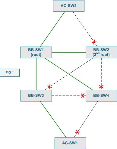
Look at Figure 1 above. It demonstrates a sample network topology (pretty poorly designed, by the way) with a backbone (core) and access layers. Everything is Layer 2 in this topology, and you can see the STP subset of the topology highlighted in green. UplinkFast extension was designed for use on access-layer switches, such as AC-SW1 and AC-SW2. Commonly, those switches have redundant uplinks to the core/distribution layer. If the primary uplink fails it would take 2xForward_Time for the backup uplink to come up. This is only in the case if the failure would be detected immediately, without aging the BPDU stored for the primary uplink. However, it makes sense to bring the secondary uplink up immediately, as soon as the primary’s failure has been detected, as there are no more uplinks. Even in case when the access-switch has more than two uplinks, we can still transition the next available uplink to the operational state, since the access-switch is not supposed to become a transit path for any traffic. If the access-switch could become a transit point, we cannot use the same trick, as this might introduce loops into the active topology. Therefore, we can quickly transition the backup link into the forwarding state if:
1) The switch has only two uplinks.
2) The switch has more than two uplinks, but the STP parameters are set in such way, that the switch would never become a transit node.
The second condition could be fulfilled if we set the STP priority of the switch to a value that makes it almost impossible to become a root bridge (numerically large value) plus increasing all ports STP cost, making all transit paths via this switch less preferred. This is what Cisco calls “UplinkFast” feature. When you enable it on a switch, the failure of the root port will transition the secondary uplink (alternate port) into forwarding state almost immediately.
The last component of UplinkFast feature is quick MAC-address table re-learning. Since the primary uplink has failed, the core switches might lose the MAC addresses associated with the access switch. This will result in connectivity disruption, till the time the addresses are re-learned via the secondary path. Thus, in addition to bringing the secondary uplink up quickly, the switch will also flood it with dummy multicast frames, sourced from all the MAC addresses known to the switch. This will allow the upstream switches (the destination is multicast) to quickly re-learn the MAC addresses via the new path. Of course, the penalty is excessive network flooding with multicast frames.
BackboneFast
In the previous post, we described how STP handles inferior BPDUs. In short, classic algorithm simply ignores the potentially useful information conveyed by inferior BPDUs. Look at Figure 2 below.

What if the link between BB-SW2 and BB-SW3 fails? First, since BB-SW2 is the root, the failure of the designated port will only cause a topology change even. However, things are more complicated for BB-SW3, since it loses the root port. BB-SW3 will invalidate the currently know root bridge information, and try looking for another alternative. Since the port on BB-SW4 connected to BB-SW3 is blocking, there is now new information. Thus BB-SW3 declares itself the root of the STP and starts sending inferior BPDUs to BB-SW4. If the latter would be a classic STP switch, it would ignore the inferior information until the BPDU stored with the blocked port expires (around Max_Age seconds). However, with BackBone fast enable, the switch that receives inferior information will attempt to verify if this failure affected its own connection to the root (e.g. whether the current root bridge is actually dead or we lost the connection to it just like our neighbor).
1) The switch selects the root port and all alternate ports (all upstream ports) as the candidate paths to the current root. In case of BB-SW4 there is just one root link to BB-SW2 and there is ALN path via BB SW3. The switch then sends out special RLQ (Root Link Query) BPDUs out of the selected ports, in our case to BB-SW4 and BB-SW3. What these BPDUs contain is the following (among other fields):
a) The Bridge ID of the querying switch (local switch BID)
b) The Bridge ID of our current Root Bridge (or what the querying switch thinks is the current root bridge).
2) Every switch that receives the RLQ, checks the Root Bridge ID in the query.
2.1) If this is the same BID that receiving switch consider to be the root, it relays the RLQ upstream, across its root port.
2.2) If the switch receiving the RLQ is the root bridge itself, it floods a positive RLQ response out of ALL its designated (downstream) ports. In our situation, this is the case, and BB-SW2 immediately responds to BB-SW4.
2.3) If the switch receiving the RLQ considers a different bridge to be the root of the topology, it immediately responds with a negative RLQ, flooded out of all designated (downstream) ports.
3) RLQ responses are flooded by every switch downstream out of all designated ports. Only the switch that sees itself as the originator of the RLQ will not flood the responses further. This is how the RLQ responses are eventually delivered to the querying bridge.
4) When the originating switch receives a negative response on any upstream port, it immediately invalidates the information stored with this port, and moves it to the Listening state, starting BPDU exchange. This happens with the port connected to BB-SW3 in our case. If the answer is positive, the information stored with the port is considered to be valid. The switch waits for responses on all upstream ports, retaining or invalidating the respective stored BPDUs.
5) If ALL responses were negative, the querying switch deduces loss of the connectivity to the old root. The querying switch declares itself as the new root and starts propagating this information out of all ports, listening for better BPDUs at the same time.
6) If at least ONE response was positive, the querying switch assumes that it still has healthy connection to the current root, unblocks the ports that have received negative responses. This allows the switch to start sending information about the current root to the switch that thinks it lost connection to the root bridge. In our case, BB-SW4 receives a positive response from BB-SW2 and immediately unblocks the port to BB-SW3, starting to relay BB-SW2 configuration BPDUs.
Therefore, the overall effect of BB Fast is proactive testing of the current topology and quick invalidation of the outdated information. Backbone Fast allows saving up to Max_Age seconds of waiting to expire the old root bridge information and thus reduce the convergence time to 2xForward_Time. The BB Fast feature is only useful on switches that are capable of becoming a transit node, i.e. the switches that form the core (backbone) of the bridged network. Of course, since BB Fast uses special RLQ BPDUs, it must be explicitly enabled in all participating Cisco switches.
Finally, a quick question to think about after reading this post: Is if OK to enable the UplinkFast feature on all switches forming the “ring” topology ?
