OSPF Areas, Part 1, The Backbone Area
Thanks to one of our brilliant CCIE R/S Written students, Nish, for his request of this series of INE blog posts. Nish is still struggling a bit with the different OSPF area types and how exactly they impact Link State Advertisements (LSAs). In this series, we will tackle each of the different OSPF areas in great detail, confirming our Level 1 knowledge at the command line as we progress.
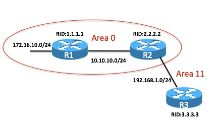
Here is the network we will use in this first post. Notice this simple network can be constructed easily in Dynamips, or with three pretty basic Cisco routers capable of OSPF version 2.

To prepare for this blog post, we have configured all of the underlying layer 2 and 3 connectivity. We have also configured OSPF per the diagram. Note the OSPF router IDs were set using the OSPF router-mode router-id command. These addresses do not exist on the devices, and therefore they are not advertised in the protocol, and obviously, they are not reachable.
So let us examine the first device, R1. This is an internal, backbone router. What do we expect to see in the OSPF database? Well, since there is broadcast media at work in that area, I expect to see an LSA Type 2, and we have another area, Area 11, so we should also see an LSA Type 3. Here is the actual OSPF database on the device:
R1#show ip ospf databaseOSPF Router with ID (1.1.1.1) (Process ID 1)
Router Link States (Area 0)
Link ID ADV Router Age Seq# Checksum Link count
1.1.1.1 1.1.1.1 99 0x80000002 0x001FEB 2
2.2.2.2 2.2.2.2 95 0x80000002 0x007761 1Net Link States (Area 0)
Link ID ADV Router Age Seq# Checksum
10.10.10.1 1.1.1.1 99 0x80000001 0x009476Summary Net Link States (Area 0)
Link ID ADV Router Age Seq# Checksum
192.168.1.0 2.2.2.2 98 0x80000001 0x00F4CB
R1#
Interesting, OK, as an internal, backbone router, the first thing I notice is the fact that we only have one link state database here - it is for Area 0 of course. OK, very interesting, we have LSA 1 types (Router Link States) for the Router IDs of R1 and R2 in that area. Wow, these are not even valid (reachable) IP addresses in the scenario. I guess this is how we can use these Router IDs when we create a virtual link. These Router IDs are tracked and shared by the OSPF speakers.
The next entry is the LSA Type 2 (Net Link State) we expected. The advertising router is the local router (R1, RID: 1.1.1.1). We must be the Designated Router (DR), and that is indeed true. Finally, we have our LSA Type 3 (Summary Net Link State) that we expected from Area 11. Awesome. This is a fun and rewarding exercise. Predicting show command output based on our Core Knowledge (Level 1).
Now, close your eyes and think about the show command output for the OSPF database we will see in R2. This is an Area Border Router (ABR), and also a backbone router. We immediately realize we should see LSA entries for Area 0 and Area 11. This poor router has to maintain two databases:
R2#show ip ospf databaseOSPF Router with ID (2.2.2.2) (Process ID 1)
Router Link States (Area 0)
Link ID ADV Router Age Seq# Checksum Link count
1.1.1.1 1.1.1.1 905 0x80000002 0x001FEB 2
2.2.2.2 2.2.2.2 899 0x80000002 0x007761 1Net Link States (Area 0)
Link ID ADV Router Age Seq# Checksum
10.10.10.1 1.1.1.1 905 0x80000001 0x009476Summary Net Link States (Area 0)
Link ID ADV Router Age Seq# Checksum
192.168.1.0 2.2.2.2 902 0x80000001 0x00F4CBRouter Link States (Area 11)
Link ID ADV Router Age Seq# Checksum Link count
2.2.2.2 2.2.2.2 856 0x80000002 0x00F747 1
3.3.3.3 3.3.3.3 858 0x80000002 0x00B680 1Net Link States (Area 11)
Link ID ADV Router Age Seq# Checksum
192.168.1.2 2.2.2.2 859 0x80000001 0x006D44Summary Net Link States (Area 11)
Link ID ADV Router Age Seq# Checksum
10.10.10.0 2.2.2.2 904 0x80000001 0x0048C4
172.16.10.0 2.2.2.2 894 0x80000001 0x00C79B
R2#
Examine the above output line for line. There should be no surprises, and it should all fall right into place from your Core Knowledge about OSPF LSA Types now. Here is a look at the IP Routing table on this device, R2. Correlate the entries to those you see in the OSPF Database:
R2#show ip route
Codes: C - connected, S - static, R - RIP, M - mobile, B - BGP
D - EIGRP, EX - EIGRP external, O - OSPF, IA - OSPF inter area
N1 - OSPF NSSA external type 1, N2 - OSPF NSSA external type 2
E1 - OSPF external type 1, E2 - OSPF external type 2
i - IS-IS, su - IS-IS summary, L1 - IS-IS level-1, L2 - IS-IS level-2
ia - IS-IS inter area, * - candidate default, U - per-user static route
o - ODR, P - periodic downloaded static routeGateway of last resort is not set
172.16.0.0/24 is subnetted, 1 subnets
O 172.16.10.0 [110/11] via 10.10.10.1, 00:17:59, FastEthernet0/0
10.0.0.0/24 is subnetted, 1 subnets
C 10.10.10.0 is directly connected, FastEthernet0/0
C 192.168.1.0/24 is directly connected, FastEthernet0/1
R2#
In the next part of this blog series, we will look at Normal and Stub areas in OSPF. Have fun with your studies here at INE!
