The MPLS Forwarding Plane
The MPLS Architecture is divided between the Control Plane and the Data or Forwarding Plane. In this blog post we will focus on components and processes critical to the operation of the Forwarding Plane.

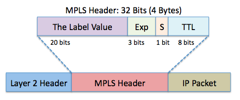
The lifeblood of the MPLS Forwarding Plane is the MPLS Header itself that is shimmed between the Layer 2 Header and the IP Header of the packet. Examine the diagram here showing this all-important MPLS Header. Notice the label itself is just one component in this Layer 2 1/2 header.

The Label Value - this 20-bit value serves as the basis for packet forwarding in the MPLS cloud. You should think of this value as an index that MPLS will use for a quick lookup in the MPLS forwarding table.
The EXP Field - these 3-bits are the Experimental Bits. They are most commonly used for Diffserv support on the MPLS network and typically carry the IP Precedence value from the IP Packet. The original Cisco proposal for Tag Switching called this field the class of service (CoS) field. However, there was no consensus within the IETF for defining this field as the CoS field. This field received its EXP bit name as a result of RFC 3032.
The Bottom of Stack Bit (S-bit) - there are many instances when MPLS headers are stacked within a packet. This bit is set on the bottom header to indicate the bottom of the stack has been reached.
Time-To-Live Field - as you would guess, this field is used for loop prevention and possibly path-tracing in the MPLS cloud. This value decrements with each hop and packet discards occur at a zero value.
In order to understand the Forwarding Plane process, let us recall our earlier Exhibit which shows a typical L3 MPLS VPN topology.

Packets arriving at the PE1 device (the Label Edge Router) have one or more MPLS Headers applied. This label identifies the egress LER to use and the Label Switching Path (LSP) the packet will follow. When the labeled packet arrives at P1 (a Label Switching Router), this device looks up the label and swaps it with the appropriate label for the outgoing interface.
At device P2 (the second to last or penultimate LSR), a default behavior occurs called Penultimate Hop Popping (PHP). This device pops (removes) the MPLS header and forwards the traffic as an IP packet to PE2 (the egress Label Edge Router). This saves workload for the PE2 device, as it simply needs to handle the "standard" IP forwarding treatment.
Since our primary concern is the L3 MPLS VPN that is the typical Lab Exam MPLS implementation, we will ultimately experience a label stacking paradigm in our MPLS studies. An inner label is used to identify our L3 VPN customer, and an outer label is used as the "transport" label, moving the data through the MPLS cloud to the egress point.
I hope you are excited for more close inspection of MPLS at work here on our blog!
