MPLS Tunnels Explained

In this blog post we’re going to discuss the fundamental logic of how MPLS tunnels allow applications such as L2VPN & L3VPN to work, and how MPLS tunnels enable Service Providers to run what is known as the “BGP Free Core”. In a nutshell, MPLS tunnels allow traffic to transit over devices that have no knowledge of the traffic’s final destination, similar to how GRE tunnels and site-to-site IPsec VPN tunnels work. To accomplish this, MPLS tunnels use a combination of IGP learned information, BGP learned information, and MPLS labels.
In normal IP transit networks, each device in the topology makes a routing decision on a hop-by-hop basis by comparing the destination IP address of the packet to the routing or forwarding table. In MPLS networks, devices make their decision based on the MPLS label contained in the packet that is received. In this manner, MPLS enabled Label Switch Routers (LSRs for short) do not necessarily need IP routing information about all destinations, as long as they know how to forward traffic based on an MPLS label. To demonstrate how this process works, we’ll examine the above topology in two sample cases, first with normal IP packet forwarding, and secondly with IP packet forwarding plus MPLS.
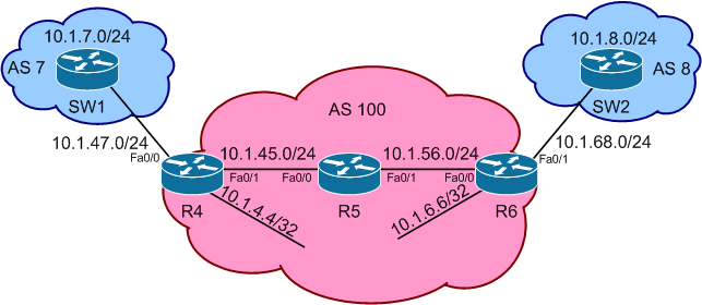
In this topology R4, R5, and R6 represent the Service Provider network, while SW1 and SW2 represent customers that are using the Service Provider for transit. In each example case, the goal of our scenario will be to provide IP packet transport between the 10.1.7.0/24 network attached to SW1, and the 10.1.8.0/24 network attached to SW2.
Case 1: Normal IP Forwarding
In case 1, the devices in the topology are configured as follows. AS 100, which consists of R4, R5, and R6, runs OSPF as an IGP on all internal interfaces, along with a full mesh of iBGP. AS 7, which consists of SW1, and AS 8, which consists of SW2, peer EBGP with AS 100 via R4 and R6 respectively, and advertise the prefixes 10.1.7.0/24 & 10.1.8.0/24 respectively into BGP. The relevant device configurations are as follows. Note that these configs assume that layer 2 connectivity has already been established between the devices.
R4#
interface Loopback0
ip address 10.1.4.4 255.255.255.255
ip ospf 1 area 0
!
interface FastEthernet0/0
ip address 10.1.47.4 255.255.255.0
!
interface FastEthernet0/1
ip address 10.1.45.4 255.255.255.0
ip ospf 1 area 0
!
router bgp 100
neighbor 10.1.6.6 remote-as 100
neighbor 10.1.6.6 update-source Loopback0
neighbor 10.1.6.6 next-hop-self
neighbor 10.1.45.5 remote-as 100
neighbor 10.1.45.5 next-hop-self
neighbor 10.1.47.7 remote-as 7R5#
interface FastEthernet0/0
ip address 10.1.45.5 255.255.255.0
ip ospf 1 area 0
!
interface FastEthernet0/1
ip address 10.1.56.5 255.255.255.0
ip ospf 1 area 0
!
router bgp 100
neighbor 10.1.45.4 remote-as 100
neighbor 10.1.56.6 remote-as 100R6#
interface Loopback0
ip address 10.1.6.6 255.255.255.255
ip ospf 1 area 0
!
interface FastEthernet0/0
ip address 10.1.56.6 255.255.255.0
ip ospf 1 area 0
!
interface FastEthernet0/1
ip address 10.1.68.6 255.255.255.0
!
router bgp 100
neighbor 10.1.4.4 remote-as 100
neighbor 10.1.4.4 update-source Loopback0
neighbor 10.1.4.4 next-hop-self
neighbor 10.1.56.5 remote-as 100
neighbor 10.1.56.5 next-hop-self
neighbor 10.1.68.8 remote-as 8SW1#
interface Loopback0
ip address 10.1.7.7 255.255.255.0
!
interface Vlan47
ip address 10.1.47.7 255.255.255.0
!
router bgp 7
network 10.1.7.0 mask 255.255.255.0
neighbor 10.1.47.4 remote-as 100SW2#
interface Loopback0
ip address 10.1.8.8 255.255.255.0
!
interface Vlan68
ip address 10.1.68.8 255.255.255.0
!
router bgp 8
network 10.1.8.0 mask 255.255.255.0
neighbor 10.1.68.6 remote-as 100
Next, let’s examine the hop-by-hop packet flow as traffic moves between the 10.1.7.0/24 and 10.1.8.0/24 networks, starting at SW1 towards SW2, and then back in the reverse direction. Note that verification should be done in both directions, as packet flow from the source to destination is independent of packet flow from the destination back to the source.
SW1#show ip route 10.1.8.0

Routing entry for 10.1.8.0/24

  Known via "bgp 7", distance 20, metric 0

  Tag 100, type external

  Last update from 10.1.47.4 00:21:13 ago

  Routing Descriptor Blocks:

  * 10.1.47.4, from 10.1.47.4, 00:21:13 ago

      Route metric is 0, traffic share count is 1

      AS Hops 2

      Route tag 100
On SW1, the prefix 10.1.8.0 is learned via BGP from R4, with a next-hop of 10.1.47.4. Next, SW1 performs a second recursive lookup on the next-hop to see which interface must be used for packet forwarding.
SW1#show ip route 10.1.47.4

Routing entry for 10.1.47.0/24

  Known via "connected", distance 0, metric 0 (connected, via interface)

  Routing Descriptor Blocks:

  * directly connected, via Vlan47

      Route metric is 0, traffic share count is 1
The result of this lookup is that SW1 should use interface Vlan47, which connects towards R4. Assuming that underlying IP address to MAC address resolution is successful, packets going to 10.1.8.0 should be properly routed towards R4. Next, the lookup process continues on R4.
R4#show ip route 10.1.8.0

Routing entry for 10.1.8.0/24

  Known via "bgp 100", distance 200, metric 0

  Tag 8, type internal

  Last update from 10.1.6.6 00:25:19 ago

  Routing Descriptor Blocks:

  * 10.1.6.6, from 10.1.6.6, 00:25:19 ago

      Route metric is 0, traffic share count is 1

      AS Hops 1

      Route tag 8
R4 is learning the prefix 10.1.8.0 via iBGP from R6, with a next-hop value of 10.1.6.6, R6’s Loopback0 interface. R4 must now perform an additional recursive lookup to figure out what interface 10.1.6.6 is reachable out.
R4#show ip route 10.1.6.6

Routing entry for 10.1.6.6/32

  Known via "ospf 1", distance 110, metric 3, type intra area

  Last update from 10.1.45.5 on FastEthernet0/1, 00:25:26 ago

  Routing Descriptor Blocks:

  * 10.1.45.5, from 10.1.6.6, 00:25:26 ago, via FastEthernet0/1

      Route metric is 3, traffic share count is 1
R4 knows 10.1.6.6 via OSPF from R5, which uses interface FastEthernet0/1. Assuming layer 2 connectivity is working properly, packets towards 10.1.8.0 are now routed to R5, and the lookup process continues.
R5#show ip route 10.1.8.0

Routing entry for 10.1.8.0/24

  Known via "bgp 100", distance 200, metric 0

  Tag 8, type internal

  Last update from 10.1.56.6 00:24:36 ago

  Routing Descriptor Blocks:

  * 10.1.56.6, from 10.1.56.6, 00:24:36 ago

      Route metric is 0, traffic share count is 1

      AS Hops 1

      Route tag 8
R5 is learning the prefix 10.1.8.0 via iBGP from R6, with a next-hop of 10.1.56.6. A recursive lookup on the next-hop, as seen below, indicates that R5 should use interface FastEthernet0/1 to forward packets towards 10.1.8.0.
R5#show ip route 10.1.56.6

Routing entry for 10.1.56.0/24

  Known via "connected", distance 0, metric 0 (connected, via interface)

  Routing Descriptor Blocks:

  * directly connected, via FastEthernet0/1

      Route metric is 0, traffic share count is 1
The lookup process now continues on R6, as seen below.
R6#show ip route 10.1.8.0

Routing entry for 10.1.8.0/24

  Known via "bgp 100", distance 20, metric 0

  Tag 8, type external

  Last update from 10.1.68.8 00:28:58 ago

  Routing Descriptor Blocks:

  * 10.1.68.8, from 10.1.68.8, 00:28:58 ago

      Route metric is 0, traffic share count is 1

      AS Hops 1

      Route tag 8
R6 is learning the prefix 10.1.8.0 via EBGP from SW2, with a next-hop of 10.1.68.8.
R6#show ip route 10.1.68.8

Routing entry for 10.1.68.0/24

  Known via "connected", distance 0, metric 0 (connected, via interface)

  Routing Descriptor Blocks:

  * directly connected, via FastEthernet0/1

      Route metric is 0, traffic share count is 1
A recursive lookup on 10.1.68.8 from R6 dictates that interface FastEthernet0/1 should be used to forward traffic on to SW2.
SW2#show ip route 10.1.8.0

Routing entry for 10.1.8.0/24

  Known via "connected", distance 0, metric 0 (connected, via interface)

  Advertised by bgp 8

  Routing Descriptor Blocks:

  * directly connected, via Loopback0

      Route metric is 0, traffic share count is 1
SW2’s lookup for 10.1.8.0 indicates that the destination is directly connected, and packets are routed to the final destination. For return traffic back to 10.1.7.0, a lookup occurs in the reverse direction similar to what we saw above, starting as SW2, and moving to R6, R5, R4, and then finally SW1.
This example shows how the hop-by-hop routing paradigm works in IPv4 networks. While this type of design works, one of the limitations of IPv4 forwarding is that all devices in the transit path must have routing information for all destinations they are forwarding packets towards. If AS 100 was used for Internet transit in this example, each router in the transit path would need 300,000+ routes in their routing tables in order to provide transit to all Internet destinations. This is just one of the many applications for which MPLS can be helpful. By introducing MPLS into this design, the need for large routing tables can be avoided in the core of the Service Provider network.
Case 2: MPLS Forwarding
By enabling MPLS in the Service Provider network of AS 100, BGP can be disabled in the core, lightening the load on devices that are possibly already taxed for resources. The configuration for MPLS in this scenario is very simple, but the understanding of what happens behind the scenes can be intimidating when learning the technology for the first time. To help with this learning curve, we’ll look at the step by step process that occurs when an MPLS tunnel is functional in AS 100.
The configuration changes necessary to implement MPLS in AS 100 are as follows:
R4#
mpls label protocol ldp
!
interface FastEthernet0/1
mpls ip
!
router bgp 100
no neighbor 10.1.45.5 remote-as 100R5#
mpls label protocol ldp
!
interface FastEthernet0/0
mpls ip
!
interface FastEthernet0/1
mpls ip
!
no router bgp 100R6#
mpls label protocol ldp
!
interface FastEthernet0/0
mpls ip
!
router bgp 100
no neighbor 10.1.56.5 remote-as 100
Once MPLS is enabled inside AS 100, BGP can be disabled on R5, and the additional BGP peering statements removed on R4 and R6. The end result of this change is surprising for some, as seen below.
R5#show ip route 10.1.7.0
% Subnet not in table
R5#show ip route 10.1.8.0
% Subnet not in tableSW1#ping 10.1.8.8 source 10.1.7.7
Type escape sequence to abort.
Sending 5, 100-byte ICMP Echos to 10.1.8.8, timeout is 2 seconds:
Packet sent with a source address of 10.1.7.7
!!!!!
Success rate is 100 percent (5/5), round-trip min/avg/max = 1/4/9 ms
Although R5 no longer has a route to the prefixes 10.1.7.0/24 or 10.1.8.0/24, it can still provide transit for traffic between them. How is this possible you may ask? The key is that an MPLS tunnel has now been formed between the ingress and egress routers of the Service Provider network, which are R4 and R6 in this case. To see the operation of the MPLS tunnel, we'll follow the same lookup process as before, but now R4, R5, and R6 will add an additional MPLS label lookup.
Below SW1 looks up the route for 10.1.8.0/24, and finds that it recurses to R4's next-hop value reachable via the Vlan47 interface.
SW1#show ip route 10.1.8.0
Routing entry for 10.1.8.0/24
Known via "bgp 7", distance 20, metric 0
Tag 100, type external
Last update from 10.1.47.4 01:02:56 ago
Routing Descriptor Blocks:
* 10.1.47.4, from 10.1.47.4, 01:02:56 ago
Route metric is 0, traffic share count is 1
AS Hops 2
Route tag 100SW1#show ip route 10.1.47.4
Routing entry for 10.1.47.0/24
Known via "connected", distance 0, metric 0 (connected, via interface)
Routing Descriptor Blocks:
* directly connected, via Vlan47
Route metric is 0, traffic share count is 1
Next, R4 receives packets for this destination and performs its own lookup.
R4#show ip route 10.1.8.0

Routing entry for 10.1.8.0/24

 Known via "bgp 100", distance 200, metric 0

 Tag 8, type internal

 Last update from 10.1.6.6 01:05:15 ago

 Routing Descriptor Blocks:

 * 10.1.6.6, from 10.1.6.6, 01:05:15 ago

 Route metric is 0, traffic share count is 1

 AS Hops 1

 Route tag 8
Like before, R4 finds the route via BGP from R6, with a next-hop of 10.1.6.6. R4 must now perform a recursive lookup on 10.1.6.6 to find the outgoing interface to reach R6.
R4#show ip route 10.1.6.6

Routing entry for 10.1.6.6/32

 Known via "ospf 1", distance 110, metric 3, type intra area

 Last update from 10.1.45.5 on FastEthernet0/1, 01:06:22 ago

 Routing Descriptor Blocks:

 * 10.1.45.5, from 10.1.6.6, 01:06:22 ago, via FastEthernet0/1

 Route metric is 3, traffic share count is 1
R4's recursive lookup finds the outgoing interface FastEthernet0/1 with a next-hop of 10.1.45.5. In normal IP forwarding, the packet would now be sent to the interface driver for layer 2 encapsulation. However in this case, R4 first checks to see if the interface FastEthernet0/1 is MPLS enabled, as seen below.
R4#show mpls interfaces

Interface              IP            Tunnel   BGP Static Operational

FastEthernet0/1        Yes (ldp)     No       No  No     Yes
Since interface FastEthernet0/1 is running MPLS via Label Distribution Protocol (LDP), R4 now consults the MPLS Label Forwarding Information Base (LFIB) to see if there is an MPLS label assigned to the next-hop we're trying to reach, 10.1.6.6.
R4#show mpls forwarding-table

Local  Outgoing      Prefix            Bytes Label   Outgoing   Next Hop

Label  Label or VC   or Tunnel Id      Switched      interface

16     Pop Label     10.1.56.0/24      0             Fa0/1      10.1.45.5

17     17            10.1.6.6/32       0             Fa0/1      10.1.45.5

18     18            10.1.68.0/24      0             Fa0/1      10.1.45.5
R4 finds an entry for 10.1.6.6/32 in the LFIB, and uses the outgoing label value of 17. This means that for traffic going to 10.1.8.0/24, the label 17 will be added to the packet header. In reality this lookup process occurs as one step, which is the lookup in the CEF table. The below output of the CEF table for the final destination on R4 shows that label 17 will be used, because it is inherited from the next-hop of 10.1.6.6.
R4#show ip cef 10.1.8.0 detail

10.1.8.0/24, epoch 0

 recursive via 10.1.6.6

 nexthop 10.1.45.5 FastEthernet0/1 label 17
Now that the MPLS label lookup is successful, the packet is label switched to R5, which leads us to the key step in this example. When R5 receives the packet, it sees that it has an MPLS label in the header. This means that R5 performs a lookup in the MPLS LFIB first, and not in the regular IP routing table. Specifically R5 sees the label number 17 coming in, which has a match in the LFIB as seen below.
R5#show mpls forwarding-table
Local Outgoing Prefix Bytes Label Outgoing Next Hop
Label Label or VC or Tunnel Id Switched interface
16 Pop Label 10.1.4.4/32 15447 Fa0/0 10.1.45.4
17 Pop Label 10.1.6.6/32 15393 Fa0/1 10.1.56.6
18 Pop Label 10.1.68.0/24 0 Fa0/1 10.1.56.6
The local label 17 is associated with the destination 10.1.6.6/32. Although our packets are going to the final destination 10.1.8.0/24, knowing how to get towards the next-hop 10.1.6.6/32 is sufficient for R5, because we know that R6 actually does have the route for the final destination. Specifically R5's operation at this point is to remove the label 17 from the packet, and continue to forward the packet towards R6 without an additional label. This operation is known as the "pop" operation, or label disposition. This occurs because R5 sees the outgoing label as "no label", which causes it to remove any MPLS labels from the packet, and continue forwarding it.
On the return trip for packets from 10.1.8.0/24 back to 10.1.7.0/24, R6 adds the label 16 and forwards the packet to R5, then R5 removes the label 16 and forwards the packet to R4. This can be inferred from the LFIB and CEF table verifications below.
R6#show mpls forwarding-table
Local Outgoing Prefix Bytes Label Outgoing Next Hop
Label Label or VC or Tunnel Id Switched interface
16 16 10.1.4.4/32 0 Fa0/0 10.1.56.5
17 Pop Label 10.1.45.0/24 0 Fa0/0 10.1.56.5R6#show ip cef 10.1.7.0 detail
10.1.7.0/24, epoch 0
recursive via 10.1.4.4
nexthop 10.1.56.5 FastEthernet0/0 label 16R5#show mpls forwarding-table
Local Outgoing Prefix Bytes Label Outgoing Next Hop
Label Label or VC or Tunnel Id Switched interface
16 No Label 10.1.4.4/32 17606 Fa0/0 10.1.45.4
17 No Label 10.1.6.6/32 17552 Fa0/1 10.1.56.6
18 Pop Label 10.1.68.0/24 0 Fa0/1 10.1.56.6
To see this operation in action, we can send traffic from 10.1.7.0/24 to 10.1.8.0/24, and look at the debug mpls packet output on R5.
R5#debug mpls packet
Packet debugging is onSW1#ping 10.1.8.8 source 10.1.7.7
Type escape sequence to abort.
Sending 5, 100-byte ICMP Echos to 10.1.8.8, timeout is 2 seconds:
Packet sent with a source address of 10.1.7.7
!!!!!
Success rate is 100 percent (5/5), round-trip min/avg/max = 1/4/9 msR5#
MPLS les: Fa0/0: rx: Len 118 Stack {17 0 254} - ipv4 data
MPLS les: Fa0/1: rx: Len 118 Stack {16 0 254} - ipv4 data
MPLS les: Fa0/0: rx: Len 118 Stack {17 0 254} - ipv4 data
MPLS les: Fa0/1: rx: Len 118 Stack {16 0 254} - ipv4 data
MPLS les: Fa0/0: rx: Len 118 Stack {17 0 254} - ipv4 data
MPLS les: Fa0/1: rx: Len 118 Stack {16 0 254} - ipv4 data
MPLS les: Fa0/0: rx: Len 118 Stack {17 0 254} - ipv4 data
MPLS les: Fa0/1: rx: Len 118 Stack {16 0 254} - ipv4 data
MPLS les: Fa0/0: rx: Len 118 Stack {17 0 254} - ipv4 data
MPLS les: Fa0/1: rx: Len 118 Stack {16 0 254} - ipv4 data
The beauty of this MPLS design is that for any new routes AS 7 or AS 8 advertise into the network, AS 100 does not need to allocate new MPLS labels in the core. As long as MPLS transport is established between the BGP peering address of the Provider Edge routers (R4 and R6 in this case), traffic for any destinations can transit over the Service Provider's network without the core needing any further forwarding information.
R4#show ip route 10.1.6.6
Routing entry for 10.1.6.6/32
Known via "ospf 1", distance 110, metric 3, type intra area
Last update from 10.1.45.5 on FastEthernet0/1, 01:06:22 ago
Routing Descriptor Blocks:
* 10.1.45.5, from 10.1.6.6, 01:06:22 ago, via FastEthernet0/1
Route metric is 3, traffic share count is 1R4#show mpls interfaces
Interface IP Tunnel BGP Static Operational
FastEthernet0/1 Yes (ldp) No No No Yes
R4#show mpls forw
R4#show mpls forwarding-table
Local Outgoing Prefix Bytes Label Outgoing Next Hop
Label Label or VC or Tunnel Id Switched interface
16 Pop Label 10.1.56.0/24 0 Fa0/1 10.1.45.5
17 17 10.1.6.6/32 0 Fa0/1 10.1.45.5
18 18 10.1.68.0/24 0 Fa0/1 10.1.45.5
R4#show ip cef 10.1.8.0 detail
10.1.8.0/24, epoch 0
recursive via 10.1.6.6
nexthop 10.1.45.5 FastEthernet0/1 label 17
We recently created a new self-paced MPLS course, which walks the learner step by step from concept to implementation for MPLS and L3 VPNs. Click here for more information.
