Understanding Advanced PIM Shared Tree Designs
I recently received an email from a student with a question about an example I did in our multicast bootcamp. After an hour into testing and drafting my email response, I realized this commonly misunderstood multicast design would make a great blog writeup! The original question is as follows:
Dear Brian
I am a customer of INE and bought the multicast bootcamp. Maybe I missed some important note, but I am confused related to the issue mentioned below. I am following the test bed you have shown in the presentation while describing the theory of sparse mode (Day 1 - Part 6) in which you have explained the RP Register, Join and SPT-Join.
Suppose the two trees are established, and traffic is flowing from the source to RP, and then RP to receiver. Also suppose that SPT-Join is disabled (e.g. threshold is infinity), and traffic always follows the shared trees.
Suppose that the multicast traffic flow is initiated from the source to the RP as follows:
R2 --> R4 --> R3 (RP)
Then traffic flows from the RP to receiver:
R3 --> R4 -->R5
When multicast traffic is coming from the RP on R4, will RPF check fail? I assume so, since multicast traffic is entering the interface in which RPF will be failed. Is there any other rule to follow if traffic is coming from RP?
Best Regards
Karim
Hi Karim,
First let’s do a quick recap on the different trees that are formed in PIM sparse mode. When a client wants to receive traffic for a particular group, it sends a (*,G) IGMP Report (a join) onto its LAN segment. The multicast router on this LAN segment turns the IGMP join message into a PIM Join message, and sends it upstream towards the RP. The result of this is a (*,G) shared tree rooted at the RP, which points down towards the receiver. This is considered the RPT, or simply the “shared tree”.
Next, the source of traffic begins sending multicast packets to this particular group onto its LAN segment. The multicast router on this LAN, the PIM DR, receives the feed and now knows about the source and group pair (S,G). Subsequently, the PIM DR sends a PIM Register message to the RP, informing it about the new (S,G) pair. Assuming that the rest of the PIM design is correct, e.g. no RPF failure or missing routes, the RP acknowledges the DR by replying with a PIM Register Stop message. Now the RP knows about the source via the (S,G) pair that was registered, and it knows about the receiver via the (*,G) join that came from downstream. At this point, the RP now needs to join the (S,G) tree to actually receive the traffic from the source. This is done via an (S,G) PIM Join up the reverse path towards the source. The result is a tree rooted at the source destined for the RP. This is considered the SPT, or simply the “shortest path tree”.
At this point traffic flows from the sender to the RP via the shortest path tree, and then from the RP down to the receiver via the shared tree. In many designs it is not an optimal path to have traffic flow through the RP, so the router attached to the receiver can optimize the traffic flow by joining a new shortest path tree, and then leaving the shared tree. This is accomplished by sending a SPT join, basically an (S,G) join, back towards the source, and then leaving the shared tree by sending a (*,G) prune up towards the RP. Once this process is complete, traffic can flow from the sender to the receiver without having to first go through the RP, assuming the RP isn’t already in the shortest path. Also note that this is the default behavior of PIM sparse mode.
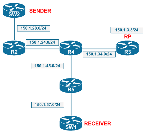
For the purpose of this example we’ll ignore this last point about the SPT join, because as you requested “Suppose that SPT-Join is disabled (e.g. threshold is infinity), and traffic always follow the shared trees.” Now let’s take a look at the specific topology that will be used for this example, as seen below. R3 is the RP, SW2 is the sender, and SW1 is the receiver. Assume that IGP is enabled everywhere, PIM sparse mode is enabled on all transit links, all devices agree that R3’s address 150.1.3.3 is the RP address, and R5 has the ip pim spt-threshold infinity command configured so it won’t initiate an SPT join.

Now following the rules of how trees should be built, let’s think about how the traffic flow should look when a feed starts at SW2 and is received by SW1. Assuming SW1 joins the group first, a (*,G) IGMP join message will be sent up to R5. R5 will see that R3 is the RP for this group, and send a (*,G) PIM join message towards R4 which is destined for R3. R4 in turn forwards the (*,G) join to R3. At this point R3, R4, and R5 have the (*,G) state pointing down towards SW1. Next, traffic from the sender, SW2, begins to flow.
R2 receives the multicast feed from SW2, and sends an (S,G) PIM Register message to R3. R3 replies back with PIM Register Stop. At this point both R2 and R3 have the (S,G) entry installed, but no one else in the network does. R3 now realizes that it knows both the sender and the receiver, so it sends a new (S,G) PIM Join to R4 that is destined for R5. Once this is successful, R2, R4, and R3 have the (S,G) state installed in the multicast routing table. The actual packet flow should then look as follows:
• SW2 sends the feed
• R2 uses the (S,G) tree to forward the packets to R4
• R4 uses the (S,G) tree to forward the packets to R3
• R3 uses the (*,G) tree to forward the packets to R4
• R4 uses the (*,G) tree to forward the packets to R5
• R5 uses the (*,G) tree to forward the packets to SW1
If this were to be the case, there would technically be a traffic loop in the topology. This is because R4 sends the feed to R3 using the (S,G) tree, but R3 sends it right back to R4 using the (*,G) tree. Even if the packets don’t loop infinitely, shouldn’t we at least see an RPF failure on R4 for the packets that are received back from R3? The answer is… yes and no :) When traffic follows this tree, RPF failure will occur on R4 and the packets will be dropped. However, PIM SM fixes this problem by automatically optimizing the merging of the SPT and the RPT on the device where both of the trees converge. In reality the traffic flow will look like this:
• SW2 sends the feed
• R2 uses the (S,G) tree to forward the packets to R4
• R4 uses the (S,G) tree to forward the packets to R5
• R5 uses the (*,G) tree to forward the packets to SW1
While this result seems to break the logic of forming the SPT and the RPT, it’s actually the normal behavior per the RFC. I actually tried finding the specific portion in the RFC that mentions this, but the section that defines Join/Prune state management is basically written in programming logic. If you’re feeling adventurous, you can find the details in RFC 4601 - Protocol Independent Multicast - Sparse Mode (PIM-SM). Specifically this logic should be part of section 4.5. PIM Join/Prune Messages, but good luck finding it :) Instead, let’s use the IOS CLI to demonstrate the final result of this design.
Refer to the diagram above for topology information. Our first step is to configure the receiver to join a group:
SW1#config t

Enter configuration commands, one per line.  End with CNTL/Z.

SW1(config)#interface Vlan57

SW1(config-if)#ip igmp join-group 224.1.1.1

SW1(config-if)#end

SW1#
At this point the (*,G) join for the RPT should be propagated up to the RP, R3. This can be seen in the below debug output.
R3#debug ip pim
PIM debugging is onPIM(0): Received v2 Join/Prune on FastEthernet0/0.34 from 150.1.34.4, to us
PIM(0): Join-list: (*, 224.1.1.1), RPT-bit set, WC-bit set, S-bit set
PIM(0): Check RP 150.1.3.3 into the (*, 224.1.1.1) entry
PIM(0): Add FastEthernet0/0.34/150.1.34.4 to (*, 224.1.1.1), Forward state, by PIM *G Join
R3, R4, and R5 should now have the (*,G) entry in the multicast routing table. The incoming interfaces point up towards the RP, while the outgoing interfaces point down towards SW1, the receiver.
R3#show ip mroute 224.1.1.1 | begin ^\(
(*, 224.1.1.1), 00:01:14/00:03:13, RP 150.1.3.3, flags: S
Incoming interface: Null, RPF nbr 0.0.0.0
Outgoing interface list:
FastEthernet0/0.34, Forward/Sparse, 00:01:14/00:03:13R4#show ip mroute 224.1.1.1 | begin ^\(
(*, 224.1.1.1), 00:01:23/00:03:06, RP 150.1.3.3, flags: S
Incoming interface: FastEthernet0/0.34, RPF nbr 150.1.34.3
Outgoing interface list:
FastEthernet0/0.45, Forward/Sparse, 00:01:23/00:03:06R5#show ip mroute 224.1.1.1 | begin ^\(
(*, 224.1.1.1), 00:01:25/00:02:02, RP 150.1.3.3, flags: SC
Incoming interface: FastEthernet0/0.45, RPF nbr 150.1.45.4
Outgoing interface list:
FastEthernet0/0.57, Forward/Sparse, 00:01:25/00:02:02
Now the source, SW2, begins generating traffic:
SW2#ping 224.1.1.1 repeat 100Type escape sequence to abort.
Sending 100, 100-byte ICMP Echos to 224.1.1.1, timeout is 2 seconds:
..
Reply to request 2 from 150.1.57.7, 8 ms
Reply to request 3 from 150.1.57.7, 8 ms
R3 receives the register message from R2 about the (S,G) pair, decapsulates the register, forwards the traffic down the (*,G) tree, and then joins the SPT back to 150.1.28.8.
PIM(0): Received v2 Register on FastEthernet0/0.34 from 150.1.24.2

     for 150.1.28.8, group 224.1.1.1

PIM(0): Insert (150.1.28.8,224.1.1.1) join in nbr 150.1.34.4's queue

PIM(0): Forward decapsulated data packet for 224.1.1.1 on FastEthernet0/0.34

PIM(0): Building Join/Prune packet for nbr 150.1.34.4

PIM(0): Adding v2 (150.1.28.8/32, 224.1.1.1), S-bit Join

PIM(0): Send v2 join/prune to 150.1.34.4 (FastEthernet0/0.34)
R3 is now joined to the SPT, and is the root of the RPT. The result is that R4 receives redundant packets, as seen from the below debug.
R4#debug ip mpacket
IP multicast packets debugging is onIP(0): s=150.1.28.8 (FastEthernet0/0.24) d=224.1.1.1 (FastEthernet0/0.45) id=353, ttl=253, prot=1, len=100(100), mforward
IP(0): s=150.1.28.8 (FastEthernet0/0.34) d=224.1.1.1 id=353, ttl=253, prot=1, len=114(100), not RPF interface
R4 now tells R3 to leave the SPT, because the traffic flow is redundant:
R4#

PIM(0): Insert (150.1.28.8,224.1.1.1) sgr prune in nbr 150.1.34.3's queue

PIM(0): Building Join/Prune packet for nbr 150.1.34.3

PIM(0):  Adding v2 (150.1.28.8/32, 224.1.1.1), RPT-bit, S-bit Prune

PIM(0): Send v2 join/prune to 150.1.34.3 (FastEthernet0/0.34)
R3 gets this message from R4:
R3#

PIM(0): Received v2 Join/Prune on FastEthernet0/0.34 from 150.1.34.4, to us

PIM(0): Prune-list: (150.1.28.8/32, 224.1.1.1) RPT-bit set
R3 has both the (*,G) and the (S,G), but the (S,G) is now pruned:
R3#show ip mroute 224.1.1.1 | begin ^\(
(*, 224.1.1.1), 00:05:59/stopped, RP 150.1.3.3, flags: S
Incoming interface: Null, RPF nbr 0.0.0.0
Outgoing interface list:
FastEthernet0/0.34, Forward/Sparse, 00:05:59/00:03:26(150.1.28.8, 224.1.1.1), 00:00:03/00:02:58, flags: PTX
Incoming interface: FastEthernet0/0.34, RPF nbr 150.1.34.4
Outgoing interface list: Null
R4 is on the SPT for the (S,G), but does not forward the traffic towards the RP
R4#show ip mroute 224.1.1.1 | begin ^\(
(*, 224.1.1.1), 00:06:27/stopped, RP 150.1.3.3, flags: S
Incoming interface: FastEthernet0/0.34, RPF nbr 150.1.34.3
Outgoing interface list:
FastEthernet0/0.45, Forward/Sparse, 00:06:27/00:02:56(150.1.28.8, 224.1.1.1), 00:00:31/00:02:52, flags: T
Incoming interface: FastEthernet0/0.24, RPF nbr 150.1.24.2
Outgoing interface list:
FastEthernet0/0.45, Forward/Sparse, 00:00:31/00:02:28
R5 is only on the (*,G) RPT, since the SPT threshold was set to inifinty:
R5#show ip mroute 224.1.1.1 | begin ^\(

(*, 224.1.1.1), 00:06:36/00:02:55, RP 150.1.3.3, flags: SC

  Incoming interface: FastEthernet0/0.45, RPF nbr 150.1.45.4

  Outgoing interface list:

    FastEthernet0/0.57, Forward/Sparse, 00:06:36/00:02:55
Note that R5 is actually forwarding the packets:
R5#show ip mroute count
IP Multicast Statistics
2 routes using 1396 bytes of memory
2 groups, 0.00 average sources per group
Forwarding Counts: Pkt Count/Pkts(neg(-) = Drops) per second/Avg Pkt Size/Kilobits per second
Other counts: Total/RPF failed/Other drops(OIF-null, rate-limit etc)Group: 224.1.1.1, Source count: 0, Packets forwarded: 70, Packets received: 70
RP-tree: Forwarding: 70/1/100/0, Other: 70/0/0
So there we have it! Although R3 is initially part of the tree for this (S,G) pair, R4 quickly realizes that this path is redundant, and prunes R3 from the tree. This SPT Join and Prune process between R3 and R4 will continue as long as the source is sending traffic, because the DR will periodically refresh the Register message to the RP. Every the register is re-sent, R3 will join the SPT, then R4 will prune R3 from the SPT.
What's interesting about this is example is that it's commonly understood that with shared trees, all traffic must pass through the RP. In this case we demonstrated this is not always true; the exception is that when links from the source to the RP in the (S,G) tree are also the same links on the (*,G) tree from the RP down to the receiver, these links will automatically be pruned.
Be sure to check out our multicast bootcamp in which I show lots of these types of examples live on the command line.
Thanks for reading!
