Cisco Performance Routing (PfR) / Optimized Edge Routing (OER) - Part 1
This blog post is the first in a series covering Performance Routing (PfR) formerly known as Optimized Edge Routing (OER) that I will be publishing over the coming weeks. I decided to cover PfR in a series of blog posts contrary to a single post as PfR is a very powerful and useful feature that leverages the power of Cisco’s IOS but at the same time PfR is potentially very complicated and often confusing feature to configure and troubleshoot. Trying to cover PfR in a single blog post would be the equivalent of trying to cover OSPF in a single blog post. In fact if you compare the IOS 12.4T OSPF Configuration Guide against the Optimized Edge Routing (OER) Configuration Guide you will notice that OER documentation is nearly 35% larger.
NOTE
In this blog post the term PfR will be used in place of OER wherever possible as Cisco has started to depricate the OER terminology and commands as of IOS 15.0.
The primary focus of these blog posts will be how PfR relates to the Routing and Switching CCIE Lab Exam (PfR v2.2). The first couple posts will cover basic scenarios (static routing and BGP) with PfR, while introducing the reader to the PfR specific terminology and features as we use then and/or run across them. After we cover the basic scenarios I will get into more complicated scenarios using PfR to optimize routing based upon DSCP values, inbound routing optimization using BGP, routing based upon application response time and voice call quality. A final post will cover PfR in IOS 15.1 (PfR v3.0) and will focus on some of the newer PfR features. I will try to keep the details and complexities of PfR out of the first couple blog posts so that the reader can gain a solid grasp of PfR before moving forward. I spend roughly half a day in my new Routing and Switching CCIE 10 Day Bootcamp covering PfR as it's important for the R&S CCIE candidate has a solid understanding before attempting the CCIE Lab exam. Additionally, I personally believe that in the future the concept of centralized route control and/or route manipulation as with PfR could become more common, similar to the concept of OpenFlow. With that being said lets get started.
Performance Routing (PfR), previously called Optimized Edge Routing (OER), introduces a new concept into IP routing. With traditional routing, path selection decisions do not consider a particular path's traffic characteristics be it throughput, actual delay, packet loss, voice mean opinion score (MOS), monetary cost of a given path, or jitter. PfR enhances the classic destination-based routing concept centered on the shortest path (lowest-cost metric) by adding into the routing selection process, network performance and/or application performance aware intelligence. In the past when routing protocols were implemented in large-scale networks, routers did not have the resources to calculate the best path based upon anything other than a simple metric. Additionally, many of these networks would be considered simplistic in regard to the number of primary and redundant links compared to today's networks. With the increase in CPU power and memory available in routers today, routing based solely upon a simple metric (hop count, cost, as-path length, etc.) is not the best use of these available resources. PfR will leverage these available resources to allow routing decisions based upon additional factors namely the networks performance and/or application performance across the network. Getting the most out of your network’s available bandwidth and/or the best possible performance for your applications across the network should be one of the primary goals of any network implementation. Let's look at an example of how we can do this using PfR.
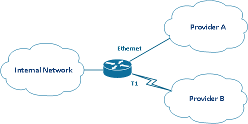
A site consisting of a single router has two connections to the Internet. One from service provider A and the other from service provider B. The link through provider A is a 10Mbps Ethernet link while the link through provider B is a 1.5Mbps T1 link. The Ethernet link is the primary path used to reach the Internet, and the T1 is used as a backup in the event the Ethernet link is down. Routing is done using static default route pointing out the Ethernet link and an additional static with a higher administrative distance (floating static) pointing out the T1 link. With this configuration, the T1 link is only used in the case the Ethernet link is down. This means the T1 link primarily sits idle for the vast majority of the time. The administrator could implement additional static routes pointing out the T1 link for networks that provider B originates to at least get some use out of the T1 but this is not an ideal solution. Ideally, the router itself will automatically select the best path for traffic based upon performance through the different service providers and/or allow traffic to overflow to the T1 link when the Ethernet link starts to become fully utilized. For simplify we will configure the latter case in this blog post.

In our scenario, the requirements are for the router to automatically move traffic flows to the T1 link when the Ethernet link becomes 75% utilized. Using traditional static routes, activating another path based upon a link's utilization is not possible without some sort of hacked up solution (EEM, TCL, packet marking with policy based routing, etc). PfR will moving these traffic flows for us. As the primary Ethernet link’s utilization rises above the 75% utilization threshold, PfR will start to look for an alternate path to route traffic flows across in order to bring down the utilization on the Ethernet link. In our scenario, PfR will automatically use NetFlow, the interface’s utilization, along with active probing with IP SLA to determine the availability of an alternate path. Knowledge of NetFlow and IP SLA is not needed as PfR manages the configuration of these technologies.
Now that we know the problem we are trying to solve let's start looking at PfR itself. For PfR, we have the concept of a Master Controller (MC) and Border Router/Routers (BR). The MC is the centralized decision maker in the PfR network. It is responsible for controlling the BRs and acts as a central location to store and analyze data collected from the BRs. The MC does not need to be in the path of the traffic flows but does need basic IP reachability to the BRs. Often in real-world medium and large-scale PfR deployments, the MC will be a dedicated router. Traditionally, the BRs are the edge routers with links to external networks (i.e. the Internet). This is where the term Optimized Edge Routing (OER) came from as we are optimizing the routing at the edge of our network but as we will see later, the added ability in the newer IOS versions for routing based upon network and/or application performance, Cisco renamed it Performance Routing (PfR). This is why today, PfR is suited for used in enterprise networks as we will see in future blog posts. The BRs are in the traffic flow paths and are responsible for collecting the NetFlow data and IP SLA probe results along with influencing the traffic flow paths by executing policy change instructions issued by the MC.

The communication between the MC and BRs uses an authenticated TCP connection on port 3949. The BR is responsible for initiating the TCP connection. In the case of a firewall or any traffic filters between the MC and BR, TCP port 3949 needs to be open in the path of the BR towards the MC. The default TCP port can be changed and the default interface used for the connection (based upon the outbound interface used to route to the MC) can be changed. The password used for authentication is done similar to how EIGRP and RIP handle authentication in IPv4, and that is through the use of key chains. Being that PfR is a path selection technology we will need to define at least one internal and two external interfaces. In our PfR setup along with the requirement of having a MC and BR will need to have at least one internal and two external interfaces on the BR. These interfaces will be defined on the MC.
NOTE
The two external interfaces are not required to be located on the same BR. One external interface could be located on one BR, and additional external interfaces could be located on another BR or even several BRs. External interfaces are not required to be physical interface and can be logical interfaces (Tunnels, Dialer, etc).
The PfR will enable NetFlow on the BR's interfaces to allow for the collection of traffic statistics to be sent back to the MC. For our first basic example, we will have the MC and BR located on the same router. Below is the diagram for this scenario:

Here is the relevant configuration for this scenario prior to configuring PfR. To ease the creation of congestion, the T1 has been clocked down to 64k, and the Ethernet link is being shaped to 256k. You will notice the floating static route pointing out the Serial link in the event the Ethernet interface goes down. This additional static route is what PfR will term a parent route for the Serial link. Since it's not important at this point, the concept of a parent route will be covered at the end of the blog post. We just need to understand that an additional route that encompasses our traffic is needed over the alternate external interface. Lastly, the load interval for the interfaces has been set to 30 seconds contrary to the default of 300 seconds. This allows PfR to react quicker to changes in the load (throughput) of the interface.
Rack1R3#show run
Building configuration...Current configuration : 2236 bytes
!
version 12.4
!
hostname Rack1R3
!
policy-map 256_SHAPE
class class-default
shape average 256000 8000 0
!
interface Loopback0
ip address 150.1.3.3 255.255.255.255
!
interface FastEthernet0/0
description Internal
ip address 204.12.1.3 255.255.255.0
!
interface FastEthernet0/1
description External
bandwidth 256
ip address 192.10.1.3 255.255.255.0
load-interval 30
service-policy output 256_SHAPE
!
interface Serial1/0
encapsulation frame-relay
load-interval 30
!
interface Serial1/0.1 point-to-point
description External
bandwidth 64
ip address 192.10.2.3 255.255.255.0
frame-relay interface-dlci 301
!
ip route 0.0.0.0 0.0.0.0 192.10.1.1
ip route 0.0.0.0 0.0.0.0 192.10.2.1 5
!
endRack1R3#show ip route
Codes: C - connected, S - static, R - RIP, M - mobile, B - BGP
D - EIGRP, EX - EIGRP external, O - OSPF, IA - OSPF inter area
N1 - OSPF NSSA external type 1, N2 - OSPF NSSA external type 2
E1 - OSPF external type 1, E2 - OSPF external type 2
i - IS-IS, su - IS-IS summary, L1 - IS-IS level-1, L2 - IS-IS level-2
ia - IS-IS inter area, * - candidate default, U - per-user static route
o - ODR, P - periodic downloaded static routeGateway of last resort is 192.10.1.1 to network 0.0.0.0
C 204.12.1.0/24 is directly connected, FastEthernet0/0
C 192.10.1.0/24 is directly connected, FastEthernet0/1
C 192.10.2.0/24 is directly connected, Serial1/0.1
150.1.0.0/32 is subnetted, 3 subnets
O 150.1.7.7 [110/2] via 204.12.1.7, 2d22h, FastEthernet0/0
O 150.1.6.6 [110/2] via 204.12.1.6, 2d23h, FastEthernet0/0
C 150.1.3.3 is directly connected, Loopback0
S* 0.0.0.0/0 [1/0] via 192.10.1.1
Rack1R3#
NOTE
With static routes it's recommended in production environments to use IP SLA and Enhanced Object Tracking to monitor the primary static route's next-hop availability if the interface's state does not indicate availability of the next-hop. This is common when a layer 2 switch is located between the local router and the next-hop.
We will start with the BR configuration. First, we need to define a key chain in the global configuration:
Rack1R3(config)#key chain OER

Rack1R3(config-keychain)#key 1

Rack1R3(config-keychain-key)#key-string CISCO

Rack1R3(config-keychain-key)#exit

Rack1R3(config-keychain)#exit

Rack1R3(config)#exit

Rack1R3#show run | section key chain

key chain OER

 key 1

   key-string CISCO

Rack1R3#
The key chain name is arbitrary and in this case, we used the name OER. We used the key numbered 1 with a key string of CISCO. For this example since the MC and BR will be located on a single router the same key chain will be used. In fact, if you change the key chain name used for the MC under the BR configuration sub-mode it will automatically change it for the BR under the MC configuration sub-mode. Some sort of idiot-proofing in the IOS ;-) Next we will configure the actual BR. On the BR we will configure the interface used to source the TCP connection off of and the IP address of the MC along with the key chain used to authenticate the session. The BR configuration is done in the OER border configuration sub-mode. To enter this mode type oer border in the global configuration.
Rack1R3(config)#oer border

Rack1R3(config-oer-br)#local Loopback0

Rack1R3(config-oer-br)#master 150.1.3.3 key-chain OER

Rack1R3(config-oer-br)#exit

Rack1R3(config)#exit

Rack1R3#show run | section oer border

oer border

 local Loopback0

 master 150.1.3.3 key-chain OER

Rack1R3#
The local command is used to control the interface the TCP session is sourced off of. This commonly is a loopback but could be any interface that has reachability to the MC. The master command is used to define the IP address of the master along with the key chain. The only other requirement for the BR is that CEF is enabled, which should be by default but remember to check that it is enabled when troubleshooting a PfR issue.
NOTE
As of IOS version 15.0 the oer keyword is changed to pfr and the oer keyword will eventually be removed from the IOS.Rack1R1(config)#do show version | include Version 15.1
Cisco IOS Software, 2800 Software (C2800NM-ADVENTERPRISEK9-M), Version 15.1(3)T2, RELEASE SOFTWARE (fc1)
Rack1R1(config)#oer ?
border Enter PfR border router configuration submode
master Enter PfR master controller configuration submodeRack1R1(config)#pfr ?
border Enter PfR border router configuration submode
master Enter PfR master controller configuration submodeRack1R1(config)#pfr border
Rack1R1(config-pfr-br)#exit
Rack1R1(config)#oer border
Rack1R1(config-pfr-br)#
Now we will configure the MC. As with the BR configuration being done in the config-oer-br configuration sub-mode, the MC will be done in similar configuration sub-mode. We will start off by entering the MC configuration sub-mode by issuing the oer master command from the global configuration. Next we will define the BR's IP address, key chain, internal and external interfaces.
Rack1R3(config)#oer master

Rack1R3(config-oer-mc)#border 150.1.3.3 key-chain OER

Rack1R3(config-oer-mc-br)#interface FastEthernet0/0 internal

Rack1R3(config-oer-mc-br)#interface Serial1/0.1 external

Rack1R3(config-oer-mc-br-if)#interface FastEthernet0/1 external

Rack1R3(config-oer-mc-br-if)#exit

Rack1R3(config-oer-mc-br)#exit

Rack1R3(config-oer-mc)#exit

Rack1R3(config)#exit

Rack1R3#show run | section oer master

oer master

 !

 border 150.1.3.3 key-chain OER

  interface FastEthernet0/0 internal

  interface Serial1/0.1 external

  interface FastEthernet0/1 external

Rack1R3#
We can now verify that the MC and BR processes on the router are communicating:
Rack1R3#show oer master
OER state: ENABLED and ACTIVE
Conn Status: SUCCESS, PORT: 3949
Version: 2.2
Number of Border routers: 1
Number of Exits: 2
Number of monitored prefixes: 0 (max 5000)
Max prefixes: total 5000 learn 2500
Prefix count: total 0, learn 0, cfg 0
PBR Requirements met
Nbar Status: InactiveBorder Status UP/DOWN AuthFail Version
150.1.3.3 ACTIVE UP 00:00:52 0 2.2
Global Settings:
max-range-utilization percent 20 recv 0
mode route metric bgp local-pref 5000
mode route metric static tag 5000
trace probe delay 1000
no logging
exit holddown time 60 secs, time remaining 0Default Policy Settings:
backoff 300 3000 300
delay relative 50
holddown 300
periodic 0
probe frequency 56
number of jitter probe packets 100
mode route observe
mode monitor both
mode select-exit good
loss relative 10
jitter threshold 20
mos threshold 3.60 percent 30
unreachable relative 50
resolve delay priority 11 variance 20
resolve range priority 12 variance 0
resolve utilization priority 13 variance 20Learn Settings:
current state : DISABLED
time remaining in current state : 0 seconds
no throughput
no delay
no inside bgp
no protocol
monitor-period 5
periodic-interval 120
aggregation-type prefix-length 24
prefixes 100
expire after time 720
Rack1R3#show oer border
OER BR 150.1.3.3 ACTIVE, MC 150.1.3.3 UP/DOWN: UP 00:01:00,
Auth Failures: 0
Conn Status: SUCCESS
OER Netflow Status: ENABLED, PORT: 3949
Version: 2.2 MC Version: 2.2
Exits
Fa0/0 INTERNAL
Fa0/1 EXTERNAL
Se1/0.1 EXTERNAL
Rack1R3#show oer master border detail
Border Status UP/DOWN AuthFail Version
150.1.3.3 ACTIVE UP 01:25:10 0 2.2
Fa0/0 INTERNAL UP
Se1/0.1 EXTERNAL UP
Fa0/1 EXTERNAL UPExternal Capacity Max BW BW Used Load Status Exit Id
Interface (kbps) (kbps) (kbps) (%)
--------- -------- ------ ------- ------- ------ ------
Se1/0.1 Tx 64 48 0 0 UP 2
Rx 64 0 0
Fa0/1 Tx 256 192 0 0 UP 1
Rx 256 0 0
Rack1R3#
NOTE
For the PfR versions, there is a major release and minor release number. For example, PfR v2.2 in IOS 12.4T or PfR v3.0 in IOS 15.1. The "2.x" and "3.x" are the major version numbers and "x.2" and "x.0" are the minor version numbers. The PfR major version number must match between the MC and BRs. Additionally the minor release version on the MC must be equal to or greater than the BR's minor release version. The version used can be determined by issuing the show oer master on the MC and show oer border on the BR.
Now that we have our MC and BR defined along with our internal and external interfaces, we need to configure the MC to start monitoring the Ethernet link's throughput rate so that traffic can be moved to the Serial link once the 75% threshold has been breached. To do this we need to enter the learn configuration sub-mode under the MC configuration sub-mode. If you look back at the output from the show oer master command, you will notice that the default state for learning phase is disabled. Once we are under the learning configuration sub-mode we will configure the MC to starting monitoring the throughput of the traffic flows from the internal interfaces out to the external interfaces.
Rack1R3(config-oer-mc)#learn

Rack1R3(config-oer-mc-learn)#throughput

Rack1R3(config-oer-mc-learn)#do sho oer master | begin Learn

Learn Settings:

  current state : STARTED

  time remaining in current state : 358 seconds

  throughput

  no delay

  no inside bgp

  no protocol

  monitor-period 5

  periodic-interval 120

  aggregation-type prefix-length 24

  prefixes 100

  expire after time 720

Rack1R3(config-oer-mc-learn)#
The default interface utilization threshold is 75% when monitoring throughput. This can be changed under the interface configuration sub-mode for a particular BR (config-oer-mc-br-if). The value can be entered as either a percentage or absolute value. The configuration flow is as follows:
Rack1R3(config)#oer master

Rack1R3(config-oer-mc)#border 150.1.3.3 key-chain OER

Rack1R3(config-oer-mc-br)#interface FastEthernet0/1 external

Rack1R3(config-oer-mc-br-if)#max-xmit-utilization ?

  absolute    Specify the utilization as an absolute value

  percentage  Specify the utilization as a percentage of the exit's bandwidth
The MC can generate log messages containing information in regard to its operation. By default, this behavior is disabled but can be enabled by issuing the logging command under the OER master configuration sub-mode. This will help us get a better understanding of what PfR is doing without the need for show commands or enabling debugging:
Rack1R3(config)#oer master

Rack1R3(config-oer-mc)#logging
By default the MC is in a route control mode of observe. This means monitoring and reporting will occur but no policy changes will be issued by the MC to the BRs. In this mode we can view what the MC is observing and what actions it would take assuming it wasn't in observe mode. Below are the log messages from the MC when the 75% threshold is breached and the MC is in observe mode.
Oct 31 11:50:05: %OER_MC-5-NOTICE: Range OOP BR 150.1.3.3, i/f Fa0/1, percent 100. Other BR 150.1.3.3, i/f Se1/0.1, percent 0

Oct 31 11:50:05: %OER_MC-5-NOTICE: Load OOP BR 150.1.3.3, i/f Fa0/1,  load 256 policy 192

Oct 31 11:50:05: %OER_MC-5-NOTICE: Exit 150.1.3.3 intf Fa0/1 OOP, Tx BW 256, Rx BW 256, Tx Load 100, Rx Load 100

Oct 31 11:50:27: %OER_MC-5-NOTICE: NO route change, Observe mode, Prefix 114.0.1.0/24, BR 150.1.3.3, i/f Se1/0.1, Reason Delay, OOP reason Range
For our scenario, we want the BR to actually move traffic flows by injecting a more specific static route over the T1 link when the Ethernet's link utilization threshold of 75% is breached. In order to do this we need PfR to determine what is called the traffic classes from the traffic flows that are flowing through BRs from the internal interface to an external interface. When OER was first introduced in IOS 12.3(8)T only layer 3 network prefix based traffic classes were supported. In newer IOS versions, we can define traffic classes based upon the layer 4 port number, DSCP value or even application using NBAR. In this scenario, we will use automatically learned layer 3 prefix traffic classes but in future blog posts, we will manually define the traffic flows that we are interested in PfR monitoring.
Since we are going to allow PfR to learn the traffic classes, these classes will be based upon the Netflow Top Talkers and then aggregated into /24 traffic classes. By default, PfR aggregates traffic flows into /24 traffic classes before sending them to the MC. The level of aggregation can be changed using the aggregation-type prefix-length <1-32> command in the learn configuration sub-mode. Once received by the MC these traffic classes are what is called Monitored Traffic Classes or MTC for short. We will be able to view these by using the show oer master traffic-class command. What this /24 aggregation means for our scenario is that when we have two traffic flows that are not in the same /24 address space (i.e. traffic destined for 114.0.0.1 and traffic destined for 114.0.1.1) the BR will aggregate these into two traffic classes: 114.0.0.0/24 and 114.0.1.0/24. Once the threshold is breached the traffic class will be considered to be what is called Out of Policy (OOP). When this happens the MC will try to move the one of the traffic classes to the T1 link by injecting a static route for the specific traffic class (i.e. 114.0.1.0/24) out the Serial1/0.1 external interface.
To have PfR automatically learn the traffic classes and alter the static routing for our scenario, we will need to enable the learning of the prefixes and trigger the route policy change based upon the external interfaces' throughput. We could base the trigger upon delay, packet loss and/or reachability but for this simplest of cases, we're just going to use throughput. Additionally, we will need to change the MC's route control policy settings from observe (mode route observe) to route control (mode route control) so that the MC can instruct the BR to inject static routes allowing it to move traffic from the Ethernet link to the T1 link. This mode can be seen using the show oer master command.
Rack1R3#show oer master | include ^Default|mode route control

Default Policy Settings:

  mode route control

Rack1R3#conf t

Enter configuration commands, one per line.  End with CNTL/Z.

Rack1R3(config)#oer master

Rack1R3(config-oer-mc)#mode route control

Rack1R3(config-oer-mc)#learn

Rack1R3(config-oer-mc-learn)#throughput

Rack1R3(config-oer-mc-learn)#exit

Rack1R3(config-oer-mc)#exit

Rack1R3(config)#exit
NOTE
The MC will learn up to 100 of these traffic classes by default. This can be changed by using the prefixes <1-100000> command in the learn configuration sub-mode. Before IOS 12.2(15)T the IOS was limited to a maximum of 5000 prefixes, but this limitation was bumped up to 100000 in the more recent IOS versions.
Before we actually start to generate traffic flows for testing, let's take a look at our final configuration (relevant commands):
Rack1R3#show run
Building configuration...Current configuration : 2283 bytes
!
version 12.4
!
hostname Rack1R3
!
ip cef
!
key chain OER
key 1
key-string CISCO
!
oer master
logging
!
border 150.1.3.3 key-chain OER
interface FastEthernet0/0 internal
interface Serial1/0.1 external
interface FastEthernet0/1 external
!
learn
throughput
mode route control
!
!
oer border
local Loopback0
master 150.1.3.3 key-chain OER
!
policy-map 256_SHAPE
class class-default
shape average 256000 8000 0
!
interface Loopback0
ip address 150.1.3.3 255.255.255.255
!
interface FastEthernet0/0
description Internal
ip address 204.12.1.3 255.255.255.0
!
interface FastEthernet0/1
description External
bandwidth 256
ip address 192.10.1.3 255.255.255.0
load-interval 30
service-policy output 256_SHAPE
!
interface Serial1/0
encapsulation frame-relay
load-interval 30
!
interface Serial1/0.1 point-to-point
description External
bandwidth 64
ip address 192.10.2.3 255.255.255.0
frame-relay interface-dlci 301
!
ip route 0.0.0.0 0.0.0.0 192.10.1.1
ip route 0.0.0.0 0.0.0.0 192.10.2.1 5
!
end
Next we're going to start with the actual testing. First off, we're going to reset the MC's state by issuing the clear oer master * command. Next we will generate a large ICMP flow by pinging from behind R3 (204.12.1.6) out to 114.0.0.1. The packet size is set to 1400, repeat 10000000 and timeout is set to 0. This will cause the BR's external Ethernet link to exceed the 75% threshold of 192k (256k * .75). Next we will telnet to 114.0.1.1 from behind R3 (204.12.1.5). This traffic flow will be aggregated to 114.0.1.0/24 and be moved by the MC, using a static route injected on the BR, to the T1 link.
Rack1R3#clear oer master *

Rack1R3#

Oct 31 17:55:22: %OER_MC-5-NOTICE: Uncontrol prefixes, Clear all

Oct 31 17:55:22: %OER_MC-5-NOTICE: BR 150.1.3.3 DOWN

Oct 31 17:55:22: %OER_MC-5-NOTICE: BR 150.1.3.3 IF Fa0/0 Unverified

Oct 31 17:55:22: %OER_MC-5-NOTICE: BR 150.1.3.3 IF Se1/0.1 Unverified

Oct 31 17:55:22: %OER_MC-5-NOTICE: BR 150.1.3.3 IF Fa0/1 Unverified

Oct 31 17:55:22: %OER_MC-5-NOTICE: MC Inactive

Oct 31 17:55:23: %OER_MC-5-NOTICE: Uncontrol prefixes, Exit down, BR 150.1.3.3 i/f Se1/0.1

Oct 31 17:55:23: %OER_MC-5-NOTICE: Uncontrol prefixes, Exit down, BR 150.1.3.3 i/f Fa0/1

Oct 31 17:55:23: %OER_MC-5-NOTICE: Uncontrol prefixes, Clear Application all

Oct 31 17:55:23: %OER_MC-5-NOTICE: Uncontrol prefixes, Clear prefix all

Rack1R3#

Oct 31 17:55:28: %OER_MC-5-NOTICE: BR 150.1.3.3 UP

Oct 31 17:55:29: %OER_MC-5-NOTICE: BR 150.1.3.3 IF Fa0/0 UP

Oct 31 17:55:29: %OER_MC-5-NOTICE: BR 150.1.3.3 IF Se1/0.1 UP

Oct 31 17:55:29: %OER_MC-5-NOTICE: BR 150.1.3.3 Active

Oct 31 17:55:29: %OER_MC-5-NOTICE: BR 150.1.3.3 IF Fa0/1 UP

Oct 31 17:55:29: %OER_MC-5-NOTICE: MC Active

Rack1R3#

Oct 31 17:55:59: %OER_MC-5-NOTICE: Prefix Learning STARTED

Rack1R3#

Oct 31 17:56:28: %OER_MC-5-NOTICE: Range OOP BR 150.1.3.3, i/f Fa0/1, percent 100. Other BR 150.1.3.3, i/f Se1/0.1, percent 0

Oct 31 17:56:28: %OER_MC-5-NOTICE: Load OOP BR 150.1.3.3, i/f Fa0/1,  load 256 policy 192

Oct 31 17:56:28: %OER_MC-5-NOTICE: Exit 150.1.3.3 intf Fa0/1 OOP, Tx BW 256, Rx BW 8, Tx Load 100, Rx Load 3


Oct 31 18:00:49: %OER_MC-5-NOTICE: Range OOP BR 150.1.3.3, i/f Fa0/1, percent 100. Other BR 150.1.3.3, i/f Se1/0.1, percent 0


Oct 31 18:00:49: %OER_MC-5-NOTICE: Load OOP BR 150.1.3.3, i/f Fa0/1,  load 256 policy 192


Oct 31 18:00:49: %OER_MC-5-NOTICE: Exit 150.1.3.3 intf Fa0/1 OOP, Tx BW 256, Rx BW 8, Tx Load 100, Rx Load 3


Rack1R3#


Oct 31 18:00:59: %OER_MC-5-NOTICE: Prefix Learning WRITING DATA


Rack1R3#


Oct 31 18:01:09: %OER_MC-5-NOTICE: Range OOP BR 150.1.3.3, i/f Fa0/1, percent 100. Other BR 150.1.3.3, i/f Se1/0.1, percent 0


Oct 31 18:01:09: %OER_MC-5-NOTICE: Load OOP BR 150.1.3.3, i/f Fa0/1,  load 256 policy 192


Oct 31 18:01:09: %OER_MC-5-NOTICE: Exit 150.1.3.3 intf Fa0/1 OOP, Tx BW 256, Rx BW 8, Tx Load 100, Rx Load 3


Rack1R3#


Oct 31 18:01:26: %OER_MC-5-NOTICE: Discovered Exit for Prefix 114.0.1.0/24, BR 150.1.3.3, i/f Fa0/1


Oct 31 18:01:26: %OER_MC-5-NOTICE: Discovered Exit for Prefix 114.0.0.0/24, BR 150.1.3.3, i/f Fa0/1


Rack1R3#


Oct 31 18:01:29: %OER_MC-5-NOTICE: Range OOP BR 150.1.3.3, i/f Fa0/1, percent 100. Other BR 150.1.3.3, i/f Se1/0.1, percent 0


Oct 31 18:01:29: %OER_MC-5-NOTICE: Load OOP BR 150.1.3.3, i/f Fa0/1,  load 256 policy 192


Oct 31 18:01:29: %OER_MC-5-NOTICE: Exit 150.1.3.3 intf Fa0/1 OOP, Tx BW 256, Rx BW 8, Tx Load 100, Rx Load 3


Rack1R3#


Oct 31 18:02:29: %OER_MC-5-NOTICE: Uncontrol Prefix 114.0.0.0/24, Couldn't find the best exit


Oct 31 18:02:29: %OER_MC-5-NOTICE: Uncontrol Prefix 114.0.0.0/24, Couldn't choose exit in prefix timeout


Oct 31 18:02:29: %OER_MC-5-NOTICE: Range OOP BR 150.1.3.3, i/f Fa0/1, percent 100. Other BR 150.1.3.3, i/f Se1/0.1, percent 0


Oct 31 18:02:29: %OER_MC-5-NOTICE: Load OOP BR 150.1.3.3, i/f Fa0/1,  load 256 policy 192


Oct 31 18:02:29: %OER_MC-5-NOTICE: Exit 150.1.3.3 intf Fa0/1 OOP, Tx BW 256, Rx BW 8, Tx Load 100, Rx Load 3


Oct 31 18:02:29: %OER_MC-5-NOTICE:


  Route changed Prefix 114.0.1.0/24, BR 150.1.3.3, i/f Se1/0.1, Reason Delay, OOP Reason Range


Rack1R3#
From the output of the MC logging, we can see that at 18:02:29 a static route is injected into the BR's routing table for the 114.0.1.0/24 MTC which took roughly 7 minutes from the time we restarted the MC (clear oer master *). This is the MTC for the telnet traffic flow from 204.12.1.5 to 114.0.1.1. Later, we will speed this process up and even configure PfR to switch within a matter of just a few seconds.
Rack1R3#show oer master traffic-class
OER Prefix Statistics:
Pas - Passive, Act - Active, S - Short term, L - Long term, Dly - Delay (ms),
P - Percentage below threshold, Jit - Jitter (ms),
MOS - Mean Opinion Score
Los - Packet Loss (packets-per-million), Un - Unreachable (flows-per-million),
E - Egress, I - Ingress, Bw - Bandwidth (kbps), N - Not applicable
U - unknown, * - uncontrolled, + - control more specific, @ - active probe all
# - Prefix monitor mode is Special, & - Blackholed Prefix
% - Force Next-Hop, ^ - Prefix is deniedDstPrefix Appl_ID Dscp Prot SrcPort DstPort SrcPrefix
Flags State Time CurrBR CurrI/F Protocol
PasSDly PasLDly PasSUn PasLUn PasSLos PasLLos EBw IBw
ActSDly ActLDly ActSUn ActLUn ActSJit ActPMOS ActSLos ActLLos
--------------------------------------------------------------------------------
114.0.0.0/24 N defa N N N N
DEFAULT* 21 150.1.3.3 Fa0/1 U
U U 0 0 0 0 8204 0
U U 0 1000000 N N N N114.0.1.0/24 N defa N N N N
INPOLICY 0 150.1.3.3 Se1/0.1 STATIC
20 20 0 0 0 0 1 1
U U 0 0 N N N NRack1R3#
Rack1R3#show ip route static
114.0.0.0/24 is subnetted, 1 subnets
S 114.0.1.0 [1/0] via 192.10.2.1
S* 0.0.0.0/0 [1/0] via 192.10.1.1
Rack1R3#
Rack1R3#show oer border routes staticFlags: C - Controlled by oer, X - Path is excluded from control,
E - The control is exact, N - The control is non-exactFlags Network Parent Tag
CE 114.0.1.0/24 0.0.0.0/0 5000
Rack1R3#
NOTE
The static route injected on the BR will not show up in the running configuration which means it will not be saved upon a reload. This is done to ensure if ever communication is lost between the MC and BR that any policy changes issued by the MC cannot be saved and are quickly removed.Rack1R3#show run | include ip route
ip route 0.0.0.0 0.0.0.0 192.10.1.1
ip route 0.0.0.0 0.0.0.0 192.10.2.1 5
We can now see that everything worked as expected and the traffic destined for the 114.0.1.0/24 prefix is being routed across the T1 using the static route injected by PfR over the less specific static default route. As mentioned earlier PfR uses NetFlow for collecting statistics about the traffic flows. This can be seen by using the show ip cache flow command.
Rack1R3#show ip cache flow
IP packet size distribution (65263711 total packets):
1-32 64 96 128 160 192 224 256 288 320 352 384 416 448 480
.000 .000 .000 .000 .000 .000 .000 .000 .000 .000 .000 .000 .000 .000 .000512 544 576 1024 1536 2048 2560 3072 3584 4096 4608
.000 .000 .000 .000 .999 .000 .000 .000 .000 .000 .000IP Flow Switching Cache, 278544 bytes
3 active, 4093 inactive, 3747 added
174735 ager polls, 0 flow alloc failures
Active flows timeout in 1 minutes
Inactive flows timeout in 15 seconds
IP Sub Flow Cache, 34056 bytes
8 active, 1016 inactive, 6691 added, 3747 added to flow
0 alloc failures, 0 force free
1 chunk, 20 chunks added
last clearing of statistics never
Protocol Total Flows Packets Bytes Packets Active(Sec) Idle(Sec)
-------- Flows /Sec /Flow /Pkt /Sec /Flow /Flow
TCP-Telnet 385 0.0 108 143 0.0 31.3 7.3
ICMP 2379 0.0 27404 1463 102.5 59.8 0.4
Total: 2764 0.0 23602 1462 102.6 55.9 1.4SrcIf SrcIPaddress DstIf DstIPaddress Pr SrcP DstP Pkts
Fa0/0 204.12.1.6 Fa0/1 114.0.0.1 01 0000 0800 26K
Fa0/1 114.0.1.1 Fa0/0 204.12.1.5 06 0017 3893 174
Fa0/0 204.12.1.5 Se1/0.1 114.0.1.1 06 3893 0017 256
Rack1R3#
It was mentioned earlier that by default PfR uses IP SLA along with NetFlow. Although we will go into more detail on IP SLA with PfR later, how PfR used ICMP echo probes to assist with path selection for our scenario can be seen below:
Rack1R3#show oer master active-probes
OER Master Controller active-probes
Border = Border Router running this Probe
State = Un/Assigned to a Prefix
Prefix = Probe is assigned to this Prefix
Type = Probe Type
Target = Target Address
TPort = Target Port
How = Was the probe Learned or Configured
N - Not applicableThe following Probes exist:
State Prefix Type Target TPort How Codec
Assigned 114.0.1.0/24 echo 114.0.1.1 N Lrnd N
Assigned 114.0.0.0/24 echo 114.0.0.1 N Lrnd NThe following Probes are running:
Border State Prefix Type Target TPort
150.1.3.3 ACTIVE 114.0.1.0/24 echo 114.0.1.1 N
150.1.3.3 ACTIVE 114.0.1.0/24 echo 114.0.1.1 N
150.1.3.3 ACTIVE 114.0.0.0/24 echo 114.0.0.1 N
150.1.3.3 ACTIVE 114.0.0.0/24 echo 114.0.0.1 NRack1R3#show oer border active-probes
OER Border active-probes
Type = Probe Type
Target = Target IP Address
TPort = Target Port
Source = Send From Source IP Address
Interface = Exit interface
Att = Number of Attempts
Comps = Number of completions
N - Not applicableType Target TPort Source Interface Att Comps
DSCP
echo 114.0.1.1 N 192.10.1.3 Fa0/1 1 1
0
echo 114.0.1.1 N 192.10.2.3 Se1/0.1 1 1
0
echo 114.0.0.1 N 192.10.1.3 Fa0/1 1 0
0
echo 114.0.0.1 N 192.10.2.3 Se1/0.1 1 0
0
Although this completes our relatively simple scenario, I will like to come back to the concept of the parent route briefly covered earlier. As mentioned the MC will, by default, try to aggregate traffic into /24 prefixes (traffic classes). In order for the MC to instruct the BR to inject a new static route for a particular flow out an alternate external interface, a parent route needs to already exist pointing out the alternate external interface. In our scenario, we have a floating static route pointing out the Serial1/0.1 interface. Although this static route isn't in the routing table due to the higher administrative distance, it is still needed for PfR to use the alternate interface. PfR will need to verify that the interface is useable and reachability can be obtained across the alternate external interface. In our case, PfR used IP SLA because by default PfR operates in a prefix monitoring mode of what is termed as both. The term both is referring to both active and passive monitoring. Active monitoring means that PfR will generate test traffic (probes), ICMP ECHOs in our case, to verify reachability across the alternate path out the Serial1/0.1 interface. As we will see in future blog posts, we can specify the type of test traffic we want generated. For instance, if we are using PfR to optimize VoIP traffic in our internal network, we could use VoIP voice packets with IP SLA for the active probing.
So the point here is to remember that a parent route, which is defined as a route that is equal to or less specific than the monitored traffic class (MTC), is needed but does not actually have to be in the routing table when static routes are used. Just being in the global configuration is adequate to be considered a parent route.
Valid due to the fact a parent route does exist for the alternate external interface:
Rack1R3#show run | include ip route

ip route 0.0.0.0 0.0.0.0 192.10.1.1

ip route 0.0.0.0 0.0.0.0 192.10.2.1 5
Rack1R3#show ip route static
S* 0.0.0.0/0 [1/0] via 192.10.1.1
Rack1R3#
Invalid due to the fact a parent route does not exist for the alternate external interface:
Rack1R3#show run | include ip route

ip route 0.0.0.0 0.0.0.0 192.10.1.1

Rack1R3#show ip route static

S*   0.0.0.0/0 [1/0] via 192.10.1.1

Rack1R3#
Although this blog post my seem long there are a lot of details that were left out but will be covered in future posts on PfR. In the next blog post we will define our own traffic classes based upon the DSCP values and applications for PfR to monitor along with a PfR load balancing scenario.
