Using Cisco VIRL for CCIE Preparation
Click here to download the INE VIRL topology and initial configs
After long anticipation, Cisco’s Virtual Internet Routing Lab (VIRL) is now publicly available. VIRL is a network design and simulation environment that includes a GNS3-like frontend GUI to visually build network topologies, and an OpenStack based backend which includes IOSv, IOS XRv, NX-OSv, & CSR1000v software images that run on the built-in hypervisor. In this post I’m going to outline how you can use VIRL to prepare for the CCIE Routing & Switching Version 5.0 Lab Exam in conjunction with INE’s CCIE RSv5 Advanced Technologies Labs.
The first step of course is to get a copy of VIRL. VIRL is currently available for purchase from virl.cisco.com in two forms, a “Personal Edition” for a $200 annual license, and an “Academic Version” for an $80 annual license. Functionally these two versions are the same. Next is to install VIRL on a hypervisor of your choosing, such as VMWare ESXi, Fusion, or Player. Make sure to follow the installation guides in the VIRL documentation, because the install is not a very straightforward process. When installing it on VMWare Player I ran into a problem with the NTPd not syncing, which resulted in the license key not being able to register. In my case I had to edit the /etc/ntp.conf file manually to specify a new NTP server, which isn’t listed as a step in the current install guide. If you run into problems during install check the VIRL support community, as it’s likely that someone has already run into your particular install issue, and a workaround may be listed there.
Once VIRL and VM Maestro (the GUI frontend) is up and running, the next step is to build your topology. For the INE CCIE RSv5 Advanced Technology Labs, this topology will be 10 IOS or IOS XE instances that are connected to a single vSwitch. All you need to do to build this is to add the 10 IOS instances, and then connect them all to a single "Multipoint Connection". Logical network segments will then later be built based on the initial configurations that you load on the routers for a specific lab. The end result of the topology should look something like this:

You may also want to add some basic customization to the topology file and the VM Maestro interface. I set the hostnames of the devices to R1 – R10 by clicking on the router icon, then setting the "Name" under the Properties tab.

Next under the File > Preferences > Terminal > Cisco Terminal you can set the options to use your own terminal software instead of the built in one. In my case I set the "Title format" variable to "%s", which makes it show just the hostname in the SecureCRT tab, and set the "Telnet command" to "C:\Program Files\VanDyke Software\SecureCRT\SecureCRT.exe /T /N %t /TELNET %h %p", which makes it spawn a SecureCRT tabbed window when I want to open the CLI to the routers. Your options of course may vary depending on your terminal software and its install location.

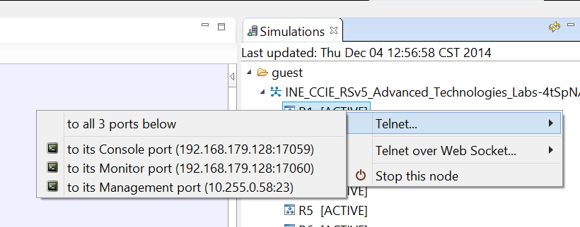
Next, click the "Launch Simulation" button on the topology to start the routers. Assuming everything is correct with your install, and you have enough CPU & memory resources, the instances should boot and show the "ACTIVE" state, similar to what you see below:

If you right click on the device name you’ll see the option to telnet to the console port. Note that the port number changes every time you restart the simulation, so I found it easier just to launch the telnet sessions from here instead of creating manual sessions under the SecureCRT database.

You should now be able to connect to the consoles of the routers and see them boot, such as you see below:
R1 con0 is now availablePress RETURN to get started.
**************************************************************************
* IOSv is strictly limited to use for evaluation, demonstration and IOS *
* education. IOSv is provided as-is and is not supported by Cisco's *
* Technical Advisory Center. Any use or disclosure, in whole or in part, *
* of the IOSv Software or Documentation to any third party for any *
* purposes is expressly prohibited except as otherwise authorized by *
* Cisco in writing. *
**************************************************************************
R1>
R1>enable
R1#show version
Cisco IOS Software, IOSv Software (VIOS-ADVENTERPRISEK9-M), Experimental Version 15.4(20141119:013030) [jsfeng-V154_3_M 107]
Copyright (c) 1986-2014 by Cisco Systems, Inc.
Compiled Tue 18-Nov-14 20:30 by jsfengROM: Bootstrap program is IOSv
R1 uptime is 46 minutes
System returned to ROM by reload
System image file is "flash0:/vios-adventerprisek9-m"
Last reload reason: Unknown reasonThis product contains cryptographic features and is subject to United
States and local country laws governing import, export, transfer and
use. Delivery of Cisco cryptographic products does not imply
third-party authority to import, export, distribute or use encryption.
Importers, exporters, distributors and users are responsible for
compliance with U.S. and local country laws. By using this product you
agree to comply with applicable laws and regulations. If you are unable
to comply with U.S. and local laws, return this product immediately.A summary of U.S. laws governing Cisco cryptographic products may be found at:
http://www.cisco.com/wwl/export/crypto/tool/stqrg.htmlIf you require further assistance please contact us by sending email to
export@cisco.com.Cisco IOSv (revision 1.0) with with 484729K/37888K bytes of memory.
Processor board ID 9B2DD0A36JBLXZY7SLJTF
2 Gigabit Ethernet interfaces
DRAM configuration is 72 bits wide with parity disabled.
256K bytes of non-volatile configuration memory.
2097152K bytes of ATA System CompactFlash 0 (Read/Write)
0K bytes of ATA CompactFlash 1 (Read/Write)
0K bytes of ATA CompactFlash 2 (Read/Write)
1008K bytes of ATA CompactFlash 3 (Read/Write)Configuration register is 0x0
R1#
With this basic topology you should have the 10 IOSv instances connected on their Gig0/1 interface to the same segment. The Gig0/0 interface is used for scripting inside the VIRL application, and can be shutdown for our purposes. The end result after the images boot should be something similar to this:
R1#show cdp neighbor
Capability Codes: R - Router, T - Trans Bridge, B - Source Route Bridge
S - Switch, H - Host, I - IGMP, r - Repeater, P - Phone,
D - Remote, C - CVTA, M - Two-port Mac RelayDevice ID Local Intrfce Holdtme Capability Platform Port ID
R9.openstacklocal
Gig 0/1 177 R B IOSv Gig 0/1
R8.openstacklocal
Gig 0/1 167 R B IOSv Gig 0/1
R3.openstacklocal
Gig 0/1 155 R B IOSv Gig 0/1
R2.openstacklocal
Gig 0/1 177 R B IOSv Gig 0/1
R7.openstacklocal
Gig 0/1 156 R B IOSv Gig 0/1
R6.openstacklocal
Gig 0/1 146 R B IOSv Gig 0/1
R5.openstacklocal
Gig 0/1 129 R B IOSv Gig 0/1
R4.openstacklocal
Gig 0/1 153 R B IOSv Gig 0/1
R10.openstacklocal
Gig 0/1 146 R B IOSv Gig 0/1Total cdp entries displayed : 9
Next you can load your initial configs for the lab you want to work on, and you’re up and running! I’ve taken the liberty of converting the CSR1000v formatted initial configs for our Advanced Technologies Labs to the IOSv format, as the two platforms use different interface numbering. Click here to download these initial configs as well as the .virl topology file that I created.
For further discussions on this see the IEOC thread Building INE's RSv5 topology on VIRL.
